Reference Guide - Propaq Encore Vital Signs Monitor - Welch Allyn
Reference Guide - Propaq Encore Vital Signs Monitor - Welch Allyn
Reference Guide - Propaq Encore Vital Signs Monitor - Welch Allyn

Create successful ePaper yourself
Turn your PDF publications into a flip-book with our unique Google optimized e-Paper software.
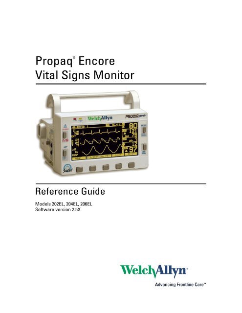
<strong>Propaq</strong> ®<br />
<strong>Encore</strong><br />
<strong>Vital</strong> <strong>Signs</strong> <strong>Monitor</strong><br />
<strong>Reference</strong> <strong>Guide</strong><br />
Models 202EL, 204EL, 206EL<br />
Software version 2.5X
ii<br />
<strong>Welch</strong> <strong>Allyn</strong> <strong>Propaq</strong> <strong>Encore</strong> <strong>Vital</strong> <strong>Signs</strong> <strong>Monitor</strong><br />
© 2008 <strong>Welch</strong> <strong>Allyn</strong>. All rights are reserved. No one is permitted to reproduce or duplicate, in any form, this manual or any part<br />
thereof without permission from <strong>Welch</strong> <strong>Allyn</strong>.<br />
<strong>Welch</strong> <strong>Allyn</strong> assumes no responsibility for any injury to anyone, or for any illegal or improper use of the product, that may result from<br />
failure to use this product in accordance with the instructions, cautions, warnings, or statement of intended use published in this<br />
manual.<br />
<strong>Welch</strong> <strong>Allyn</strong>, <strong>Propaq</strong>, Acuity, and Smartcuf are registered trademarks of <strong>Welch</strong> <strong>Allyn</strong>.<br />
SET and Masimo are registered trademarks of Masimo Corporation. Possession or purchase of a Masimo SpO 2 -equipped monitor<br />
does not convey any express or implied license to use the device with unauthorized sensors or cables which would, alone or in<br />
combination with this device, fall within the scope of one or more of the patents relating to this device.<br />
Nellcor and Oximax are registered trademarks of Nellcor Puritan Bennett.<br />
Software in this product is copyright by <strong>Welch</strong> <strong>Allyn</strong> or its vendors. All rights are reserved. The software is protected by United States<br />
of America copyright laws and international treaty provisions applicable worldwide. Under such laws, the licensee is entitled to use<br />
the copy of the software incorporated with this instrument as intended in the operation of the product in which it is embedded. The<br />
software may not be copied, decompiled, reverse-engineered, disassembled or otherwise reduced to human-perceivable form. This<br />
is not a sale of the software or any copy of the software; all right, title and ownership of the software remain with <strong>Welch</strong> <strong>Allyn</strong> or its<br />
vendors.<br />
For information about any <strong>Welch</strong> <strong>Allyn</strong> product, call the nearest <strong>Welch</strong> <strong>Allyn</strong> representative:<br />
USA + 1 315 685 4560<br />
800 535 6663<br />
REF 810-1719-XX (CD)<br />
REF 810-2106-XX (Printed, English only)<br />
Manual Part Number 810-0640-05 Ver A 2008-06<br />
Australia + 61 2 9638 3000<br />
800 074 793<br />
Canada 800 561 8797 China + 86 216 327 9631<br />
European Call Center + 35 3 46 906 7790 France + 33 1 60 09 33 66<br />
Germany + 49 7477 92 71 86 Japan + 81 3 3219 0071<br />
Latin America + 1 305 669 9003 Netherlands + 31 15 750 5000<br />
Singapore + 65 6419 8100 South Africa + 27 11 777 7555<br />
United Kingdom + 44 20 7365 6780 Sweden + 46 8 58 53 65 51<br />
<strong>Welch</strong> <strong>Allyn</strong>, Inc.<br />
8500 SW Creekside Place<br />
Beaverton, OR 97008-7107 USA<br />
<strong>Welch</strong> <strong>Allyn</strong> Ltd<br />
Navan Business Park<br />
Dublin Road, Navan<br />
County Meath, Republic of Ireland<br />
www.welchallyn.com
iii<br />
Contents<br />
1 - General information . . . . . . . . . . . . . . . . . . . . . . . . . . . . . . . . . . . . . . 1<br />
Safety summary . . . . . . . . . . . . . . . . . . . . . . . . . . . . . . . . . . . . . . . . . . . . . . . . . . 1<br />
<strong>Propaq</strong> <strong>Encore</strong> documentation . . . . . . . . . . . . . . . . . . . . . . . . . . . . . . . . . . . . . . . 5<br />
2 - Getting started. . . . . . . . . . . . . . . . . . . . . . . . . . . . . . . . . . . . . . . . . . . 7<br />
Introducing the <strong>Propaq</strong> <strong>Encore</strong> . . . . . . . . . . . . . . . . . . . . . . . . . . . . . . . . . . . . . . . 7<br />
Using the <strong>Propaq</strong> <strong>Encore</strong> . . . . . . . . . . . . . . . . . . . . . . . . . . . . . . . . . . . . . . . . . . . 9<br />
<strong>Monitor</strong> setup . . . . . . . . . . . . . . . . . . . . . . . . . . . . . . . . . . . . . . . . . . . . . . . . . . . 20<br />
Printer functions . . . . . . . . . . . . . . . . . . . . . . . . . . . . . . . . . . . . . . . . . . . . . . . . . 25<br />
Learning the <strong>Propaq</strong> <strong>Encore</strong> . . . . . . . . . . . . . . . . . . . . . . . . . . . . . . . . . . . . . . . . 26<br />
3 - Patient monitoring . . . . . . . . . . . . . . . . . . . . . . . . . . . . . . . . . . . . . . 29<br />
ECG/RESP. . . . . . . . . . . . . . . . . . . . . . . . . . . . . . . . . . . . . . . . . . . . . . . . . . . . . . 29<br />
Invasive pressure . . . . . . . . . . . . . . . . . . . . . . . . . . . . . . . . . . . . . . . . . . . . . . . . 37<br />
NIBP . . . . . . . . . . . . . . . . . . . . . . . . . . . . . . . . . . . . . . . . . . . . . . . . . . . . . . . . . . 42<br />
Temperature . . . . . . . . . . . . . . . . . . . . . . . . . . . . . . . . . . . . . . . . . . . . . . . . . . . . 50<br />
Pulse oximetry (SpO2) . . . . . . . . . . . . . . . . . . . . . . . . . . . . . . . . . . . . . . . . . . . . 52<br />
Capnography (CO2). . . . . . . . . . . . . . . . . . . . . . . . . . . . . . . . . . . . . . . . . . . . . . . 57<br />
4 - Alarms and limits . . . . . . . . . . . . . . . . . . . . . . . . . . . . . . . . . . . . . . . 69<br />
Description of alarm and alert tone patterns. . . . . . . . . . . . . . . . . . . . . . . . . . . . 69<br />
Silence an active patient alarm or equipment alert tone for 90 seconds . . . . . . 69<br />
Inhibit alarm and alert tones for four minutes: 4 SUSPND . . . . . . . . . . . . . . . . . 70<br />
Inhibit alarm and alert tones indefinitely: ALL ALARMS. . . . . . . . . . . . . . . . . . . 71<br />
Summary of alarm and alert keys and Acuity Central Station messages . . . . . . 72<br />
Alarm holdoffs . . . . . . . . . . . . . . . . . . . . . . . . . . . . . . . . . . . . . . . . . . . . . . . . . . 73<br />
Setting alarm limits . . . . . . . . . . . . . . . . . . . . . . . . . . . . . . . . . . . . . . . . . . . . . . . 74<br />
Power-up equipment alert: program fault, settings lost . . . . . . . . . . . . . . . . . . . 75<br />
Troubleshooting system error messages . . . . . . . . . . . . . . . . . . . . . . . . . . . . . . 75<br />
5 - Trends. . . . . . . . . . . . . . . . . . . . . . . . . . . . . . . . . . . . . . . . . . . . . . . . . 77<br />
The trend status window and menu. . . . . . . . . . . . . . . . . . . . . . . . . . . . . . . . . . 77<br />
How trends are accumulated . . . . . . . . . . . . . . . . . . . . . . . . . . . . . . . . . . . . . . . 77<br />
NIBP trends . . . . . . . . . . . . . . . . . . . . . . . . . . . . . . . . . . . . . . . . . . . . . . . . . . . . 78<br />
Displaying trends . . . . . . . . . . . . . . . . . . . . . . . . . . . . . . . . . . . . . . . . . . . . . . . . 78<br />
6 - Printing. . . . . . . . . . . . . . . . . . . . . . . . . . . . . . . . . . . . . . . . . . . . . . . . 79<br />
Printing patient data . . . . . . . . . . . . . . . . . . . . . . . . . . . . . . . . . . . . . . . . . . . . . . 79<br />
Printing trends . . . . . . . . . . . . . . . . . . . . . . . . . . . . . . . . . . . . . . . . . . . . . . . . . . 83<br />
7 - Acuity Central <strong>Monitor</strong>ing system. . . . . . . . . . . . . . . . . . . . . . . . . . 85<br />
Intended use. . . . . . . . . . . . . . . . . . . . . . . . . . . . . . . . . . . . . . . . . . . . . . . . . . . . 85
iv Contents <strong>Welch</strong> <strong>Allyn</strong> <strong>Propaq</strong> <strong>Encore</strong> <strong>Vital</strong> <strong>Signs</strong> <strong>Monitor</strong><br />
Connecting to the Acuity system . . . . . . . . . . . . . . . . . . . . . . . . . . . . . . . . . . . . 85<br />
Press NET OFF to disconnect from Acuity . . . . . . . . . . . . . . . . . . . . . . . . . . . . . 87<br />
Printing at Acuity. . . . . . . . . . . . . . . . . . . . . . . . . . . . . . . . . . . . . . . . . . . . . . . . . 87<br />
Network alert message . . . . . . . . . . . . . . . . . . . . . . . . . . . . . . . . . . . . . . . . . . . 88<br />
8 - Power sources . . . . . . . . . . . . . . . . . . . . . . . . . . . . . . . . . . . . . . . . . . 89<br />
Power adapter intended use. . . . . . . . . . . . . . . . . . . . . . . . . . . . . . . . . . . . . . . . 89<br />
Battery care . . . . . . . . . . . . . . . . . . . . . . . . . . . . . . . . . . . . . . . . . . . . . . . . . . . . 91<br />
9 - Care and maintenance . . . . . . . . . . . . . . . . . . . . . . . . . . . . . . . . . . . 93<br />
Avoid electrostatic discharge . . . . . . . . . . . . . . . . . . . . . . . . . . . . . . . . . . . . . . . 93<br />
Inspect and clean the monitor and accessories . . . . . . . . . . . . . . . . . . . . . . . . . 93<br />
Maintenance. . . . . . . . . . . . . . . . . . . . . . . . . . . . . . . . . . . . . . . . . . . . . . . . . . . . 94<br />
Recycling monitor components . . . . . . . . . . . . . . . . . . . . . . . . . . . . . . . . . . . . . 95<br />
<strong>Monitor</strong> care . . . . . . . . . . . . . . . . . . . . . . . . . . . . . . . . . . . . . . . . . . . . . . . . . . . . 95<br />
Printer maintenance . . . . . . . . . . . . . . . . . . . . . . . . . . . . . . . . . . . . . . . . . . . . . . 96<br />
Customer services . . . . . . . . . . . . . . . . . . . . . . . . . . . . . . . . . . . . . . . . . . . . . . . 97<br />
10 - Specifications. . . . . . . . . . . . . . . . . . . . . . . . . . . . . . . . . . . . . . . . . . 99<br />
ECG. . . . . . . . . . . . . . . . . . . . . . . . . . . . . . . . . . . . . . . . . . . . . . . . . . . . . . . . . . . 99<br />
Real-time ECG analog/defib sync . . . . . . . . . . . . . . . . . . . . . . . . . . . . . . . . . . . 101<br />
Impedance pneumography (RESP) . . . . . . . . . . . . . . . . . . . . . . . . . . . . . . . . . . 102<br />
Invasive pressure . . . . . . . . . . . . . . . . . . . . . . . . . . . . . . . . . . . . . . . . . . . . . . . 103<br />
NIBP . . . . . . . . . . . . . . . . . . . . . . . . . . . . . . . . . . . . . . . . . . . . . . . . . . . . . . . . . 104<br />
Temperature . . . . . . . . . . . . . . . . . . . . . . . . . . . . . . . . . . . . . . . . . . . . . . . . . . . 105<br />
Pulse oximetry (SpO 2 ) . . . . . . . . . . . . . . . . . . . . . . . . . . . . . . . . . . . . . . . . . . . 106<br />
Capnography (CO 2 ) . . . . . . . . . . . . . . . . . . . . . . . . . . . . . . . . . . . . . . . . . . . . . . 108<br />
Alarms. . . . . . . . . . . . . . . . . . . . . . . . . . . . . . . . . . . . . . . . . . . . . . . . . . . . . . . . 111<br />
Trends . . . . . . . . . . . . . . . . . . . . . . . . . . . . . . . . . . . . . . . . . . . . . . . . . . . . . . . . 111<br />
Display . . . . . . . . . . . . . . . . . . . . . . . . . . . . . . . . . . . . . . . . . . . . . . . . . . . . . . . 112<br />
<strong>Monitor</strong> (environmental) . . . . . . . . . . . . . . . . . . . . . . . . . . . . . . . . . . . . . . . . . . 113<br />
<strong>Monitor</strong> (physical) . . . . . . . . . . . . . . . . . . . . . . . . . . . . . . . . . . . . . . . . . . . . . . . 114<br />
Printer . . . . . . . . . . . . . . . . . . . . . . . . . . . . . . . . . . . . . . . . . . . . . . . . . . . . . . . . 115<br />
Power . . . . . . . . . . . . . . . . . . . . . . . . . . . . . . . . . . . . . . . . . . . . . . . . . . . . . . . . 116<br />
Power adapters. . . . . . . . . . . . . . . . . . . . . . . . . . . . . . . . . . . . . . . . . . . . . . . . . 117<br />
Factory default settings . . . . . . . . . . . . . . . . . . . . . . . . . . . . . . . . . . . . . . . . . . 118<br />
In-service simulated values . . . . . . . . . . . . . . . . . . . . . . . . . . . . . . . . . . . . . . . 120<br />
EMC compliance. . . . . . . . . . . . . . . . . . . . . . . . . . . . . . . . . . . . . . . . . . . . . . . . 121<br />
Glossary . . . . . . . . . . . . . . . . . . . . . . . . . . . . . . . . . . . . . . . . . . . . . . . . 125<br />
Index . . . . . . . . . . . . . . . . . . . . . . . . . . . . . . . . . . . . . . . . . . . . . . . . . . . 131
1<br />
1<br />
General information<br />
Safety summary<br />
This Safety Summary should be read by all <strong>Propaq</strong> <strong>Encore</strong> users. Specific warnings and<br />
cautions will be found throughout the <strong>Propaq</strong> <strong>Encore</strong> documentation where they apply.<br />
WARNING This monitor is to be operated by qualified personnel only. The<br />
operator of this monitor should read this entire manual, the monitor reference<br />
guide or directions for use, and all accessory directions for use before operating<br />
the monitor.<br />
WARNING Place the <strong>Propaq</strong> monitor and accessories in locations where they<br />
cannot harm the patient if they fall from their shelf or mount. Lift the monitor only<br />
by its handle; do not lift it by any attached cables.<br />
WARNING Do not connect more than one patient to a monitor. Do not connect<br />
more than one monitor to a patient.<br />
WARNING Do not use the <strong>Propaq</strong> <strong>Encore</strong> in an MRI suite or a hyperbaric<br />
chamber.<br />
WARNING Do not autoclave the <strong>Propaq</strong>. Autoclave accessories only if the<br />
manufacturer's instructions clearly approve it. Many accessories can be severely<br />
damaged by autoclaving.<br />
WARNING Inspect the power adapter cord periodically for fraying or other<br />
damage, and replace the adapter as needed. Do not operate the apparatus from<br />
mains power with a damaged power adapter cord or plug.<br />
WARNING When using a power adapter with this monitor, be sure to connect<br />
the power adapter to a three-wire, grounded, hospital-grade receptacle. Do not<br />
under any circumstances attempt to remove the grounding conductor from the<br />
power plug of the power adapter. Do not plug the power adapter into an<br />
extension cord. If there is any doubt about the integrity of the protective earth<br />
ground of the receptacle for the power adapter, do not plug in the power adapter;<br />
operate the monitor only on battery power. Contact your biomedical engineering<br />
department for assistance in identifying the proper power receptacle and making<br />
appropriate power connections.<br />
WARNING Make frequent electrical and visual checks on cables and electrode<br />
wires.<br />
WARNING Avoid electrosurgery burns at monitoring sites by ensuring proper<br />
connection of the electrosurgery return circuit so that the return paths cannot be<br />
made through monitoring electrodes and probes.
2 General information <strong>Welch</strong> <strong>Allyn</strong> <strong>Propaq</strong> <strong>Encore</strong> <strong>Vital</strong> <strong>Signs</strong> <strong>Monitor</strong><br />
WARNING During defibrillation, keep the discharge paddles away from ECG and<br />
other electrodes, as well as other conductive parts in contact with the patient.<br />
Avoid contact with any accessories connected to the <strong>Propaq</strong>’s left side panel.<br />
WARNING To ensure patient safety, the conductive parts of the ECG electrodes<br />
(including associated connectors) and other patient-applied parts should not<br />
contact other conductive parts, including earth ground, at any time.<br />
WARNING Do not operate this product in the presence of flammable<br />
anesthetics or other flammable substance in combination with air, oxygenenriched<br />
environments, or nitrous oxide; explosion can result.<br />
WARNING Within certain governmental jurisdictions, all interconnected<br />
accessory equipment must be labeled by an approved testing laboratory. After<br />
interconnection with accessory equipment, risk (leakage) current and grounding<br />
requirements must be maintained.<br />
WARNING To ensure conformance to risk (leakage) current requirements when<br />
operating from an ac mains power source, use only a <strong>Welch</strong> <strong>Allyn</strong> ® 503-0054<br />
series power adapter.<br />
WARNING This monitor should only be repaired by qualified service personnel.<br />
The operator should not attempt to open the monitor case or perform any<br />
maintenance on the monitor except for procedures explicitly described in this<br />
manual that can be performed by operators such as inspection and cleaning.<br />
WARNING To ensure patient safety, use only accessories recommended or<br />
supplied by <strong>Welch</strong> <strong>Allyn</strong>. For a list of those accessories, see Products and<br />
Accessories (810-0409-XX), which accompanies this manual. Accessories must<br />
be used according to your hospital’s standards and the manufacturer’s<br />
recommendations. Always refer to the manufacturer’s directions for use. Use of<br />
accessories not recommended by <strong>Welch</strong> <strong>Allyn</strong> may result in increased<br />
electromagnetic emissions or decreased electromagnetic immunity of the<br />
equipment.<br />
WARNING Safe interconnection between the <strong>Propaq</strong> monitor and other devices<br />
must comply with applicable medical systems safety standards such as IEC<br />
60601-1-1. Within certain governmental jurisdictions, all interconnected accessory<br />
equipment must be labeled by an approved testing laboratory. After<br />
interconnection with accessory equipment, risk (leakage) current and grounding<br />
requirements must be maintained.<br />
WARNING As with all medical equipment, carefully route the patient cabling to<br />
reduce the possibility of patient entanglement or strangulation.<br />
WARNING A product that has been dropped or severely abused should be<br />
checked by qualified service personnel to verify proper operation and acceptable<br />
risk (leakage) current values.<br />
WARNING The pulse oximetry channel should NOT be used as an apnea<br />
monitor.<br />
WARNING Do not use the pulse oximeter as a replacement or substitute for<br />
ECG-based arrhythmia analysis.
<strong>Reference</strong> <strong>Guide</strong> General information 3<br />
WARNING If the monitor detects an unrecoverable problem, an error message<br />
window appears containing an error number and a short message. Report such<br />
errors to <strong>Welch</strong> <strong>Allyn</strong>.<br />
WARNING When taking NIBP measurements, periodically observe the patient’s<br />
limb to make sure that the circulation is not impaired for a prolonged period of<br />
time. Also make sure the blood pressure cuff is properly placed according to<br />
<strong>Propaq</strong> <strong>Encore</strong> Directions for Use or <strong>Propaq</strong> <strong>Encore</strong> <strong>Reference</strong> <strong>Guide</strong>. Be<br />
especially careful when using the short-term automatic mode (TURBOCUF).<br />
Prolonged impairment of circulation or improper cuff placement can cause<br />
contusions.<br />
WARNING The range of values measured by the monitoring parameters is<br />
provided in the Specifications section of <strong>Propaq</strong> <strong>Encore</strong> Directions for Use or<br />
<strong>Propaq</strong> <strong>Encore</strong> <strong>Reference</strong> <strong>Guide</strong>. Operation of the monitor outside the range of<br />
specified values is not recommended and may cause inaccurate results.<br />
WARNING Electronic equipment that emits very strong electromagnetic or radio<br />
frequency signals can cause electrical interference with monitor operation,<br />
including causing the monitor to turn off power. Avoid operating this monitor near<br />
such equipment. For guidance about electromagnetic emissions and the<br />
recommended separation distance between the monitor and such equipment,<br />
refer to the specifications section of this manual.<br />
Symbols<br />
Caution Changes or modifications not expressly approved by <strong>Welch</strong> <strong>Allyn</strong> could<br />
void the purchaser’s authority to operate the equipment.<br />
Caution Federal (U.S.A.) law restricts this device to sale, distribution, or use by<br />
or on the order of a licensed medical practitioner.<br />
The <strong>Propaq</strong> <strong>Encore</strong> should be serviced only by a <strong>Welch</strong> <strong>Allyn</strong> service technician while<br />
under warranty. <strong>Propaq</strong> <strong>Encore</strong> Service Manual (810-0696-XX) is available from <strong>Welch</strong><br />
<strong>Allyn</strong> to assist the biomedical engineer during post-warranty period service.<br />
The following symbols may appear on the <strong>Propaq</strong> <strong>Encore</strong> monitor or accessories or<br />
documentation. These internationally recognized symbols are defined by the International<br />
Electrotechnical Commission, IEC 878 and IEC 417A.<br />
WARNING Indicates conditions that could lead to illness, injury, or death.<br />
Caution In this manual, indicates conditions that could damage equipment or other property.<br />
Caution On the product, means “Consult the accompanying documentation.”<br />
Off (Standby) Patient connections are<br />
Type CF, isolated for direct<br />
cardiac application, and<br />
protected against<br />
defibrillation.<br />
On<br />
Transformer meets<br />
requirements of a<br />
short-circuit-proof<br />
safety-isolating power<br />
transformer.<br />
Alternating current
4 General information <strong>Welch</strong> <strong>Allyn</strong> <strong>Propaq</strong> <strong>Encore</strong> <strong>Vital</strong> <strong>Signs</strong> <strong>Monitor</strong><br />
For continued fire<br />
protection, use only<br />
the specified fuse.<br />
Patient connections are<br />
Type BF, and protected<br />
against defibrillation.<br />
For indoor use only (on<br />
power adapter only)<br />
Direct current<br />
Patient connections are<br />
Type B.<br />
Caution: On the<br />
product, means<br />
“Consult<br />
accompanying<br />
documentation.”<br />
Battery charging when<br />
green indicator<br />
illuminated<br />
The CE Mark and<br />
Notified Body<br />
Registration Number<br />
signify the device has<br />
met all essential<br />
requirements of<br />
European Medical<br />
Device Directive<br />
93/42/EEC.<br />
IPX1<br />
NRTL/C<br />
Evaluated to CSA 601-1<br />
and UL2601-1<br />
Enclosure Protection Drip<br />
proof: Classification IPX1<br />
per IEC Publication 529<br />
The Canadian<br />
StandardsAssociation has<br />
evaluated this device<br />
according to CSA 601-1<br />
and Underwriters<br />
Laboratory Standard UL<br />
2601-1. (This symbol is on<br />
the Universal Power<br />
Adapter.)<br />
The CE Mark signifies<br />
the device has met all<br />
essential<br />
requirements of<br />
European Medical<br />
Device Directive<br />
93/42/EEC for a Class<br />
1 product. (This<br />
symbol is on the<br />
Universal Power<br />
Adapter.)<br />
Input port<br />
Temperature sensor<br />
input<br />
Two way<br />
communication port<br />
Output port<br />
Single-use only (not<br />
reusable).<br />
Apply the NIBP cuff as<br />
shown.<br />
NIBP cuff sizes:<br />
Thigh<br />
Large adult<br />
Adult<br />
Small adult<br />
Child<br />
Infant<br />
Pb<br />
Non-ionizing<br />
electromagnetic<br />
radiation<br />
Separate lead acid<br />
battery from other<br />
disposables for<br />
recycling<br />
Fuse<br />
Recycle the monitor and battery separately from other<br />
disposables.<br />
www.welchallyn.com/weee<br />
Temperature limits Stacking limit (by number) Altitude limit<br />
n<br />
n<br />
n%<br />
Humidity limit Keep away from rain Fragile<br />
C<br />
US<br />
This device has been tested and certified by the Canadian Standards Association International to comply<br />
with applicable U.S. and Canadian medical safety standards.
<strong>Reference</strong> <strong>Guide</strong> General information 5<br />
<strong>Propaq</strong> <strong>Encore</strong> documentation<br />
The documentation set<br />
The <strong>Propaq</strong> <strong>Encore</strong> documentation set consists of documents for the clinician, the<br />
biomedical technician, and the department head or purchaser of accessories for the<br />
<strong>Propaq</strong> <strong>Encore</strong> monitors.<br />
This <strong>Propaq</strong> <strong>Encore</strong> <strong>Reference</strong> <strong>Guide</strong> contains important safety and operating information<br />
for the clinician.<br />
<strong>Propaq</strong> <strong>Encore</strong> Service Manual (810-0696-XX) contains information on how to properly<br />
maintain the <strong>Propaq</strong> <strong>Encore</strong> through routine calibration, inspection, and maintenance.<br />
<strong>Welch</strong> <strong>Allyn</strong> Products & Accessories (810-0409-XX) provides a comprehensive list of<br />
accessories recommended for <strong>Propaq</strong> <strong>Encore</strong> monitors and options.<br />
About this reference guide<br />
This <strong>Reference</strong> <strong>Guide</strong> provides descriptions and operating information for the <strong>Propaq</strong><br />
<strong>Encore</strong> models 202EL, 204EL, and 206EL, including all available options at the time of this<br />
manual's printing.<br />
Statement of expectations of the reader<br />
This <strong>Reference</strong> <strong>Guide</strong> was written for the clinician. Although this guide may describe<br />
some monitoring techniques, <strong>Welch</strong> <strong>Allyn</strong> expects that you are a trained clinician who<br />
knows how to take and interpret a patient’s vital signs. The <strong>Propaq</strong> <strong>Encore</strong> has been<br />
designed as a quality monitor; however, inherent limitations require that good clinical<br />
judgment always prevails.
6 General information <strong>Welch</strong> <strong>Allyn</strong> <strong>Propaq</strong> <strong>Encore</strong> <strong>Vital</strong> <strong>Signs</strong> <strong>Monitor</strong>
7<br />
2<br />
Getting started<br />
Introducing the <strong>Propaq</strong> <strong>Encore</strong><br />
Intended use<br />
Before using the <strong>Propaq</strong> <strong>Encore</strong> on a patient, be sure you understand the Safety<br />
Summary at the front of this book. It provides important information about safely using<br />
the <strong>Propaq</strong> <strong>Encore</strong>. The <strong>Propaq</strong> <strong>Encore</strong> monitor is intended to be used by skilled clinicians<br />
for multiparameter vital signs monitoring of neonatal, pediatric, and adult patients in<br />
health care facility bedside applications; as well as for intra- and interfacility transport.<br />
<strong>Propaq</strong> <strong>Encore</strong> monitors that do not include CO 2 or printer options are able to withstand<br />
light rain exposure over short periods of time (uniform distribution of approximately 1 mm<br />
of water/ minute for 10 minutes or less).<br />
<strong>Propaq</strong> <strong>Encore</strong> models and options<br />
Three models of <strong>Propaq</strong> <strong>Encore</strong> monitors are available.<br />
Features common to all models<br />
206EL<br />
204EL<br />
202EL<br />
ECG, 3-lead or 5-lead configurations, 0.05-40/0.5-40 Hz<br />
NIBP, with neonatal, pediatric and adult modes<br />
Temperature, 2 channels: YSI 400 and 700 series-compatible connectors<br />
Defibrillator Synchronization<br />
Real-time Analog output of ECG<br />
Electrocautery noise suppression on all channels except Impedance<br />
Pneumography<br />
Two Invasive Pressure Channels<br />
One Invasive Pressure Channel<br />
No Invasive Pressure<br />
Options available for each model Pulse Oximetry (SpO 2 )<br />
Capnography (CO 2 ) (available only with SpO 2 ):<br />
Mainstream Capnography (MCO 2 )<br />
Sidestream Capnography (SCO 2 )<br />
Dualstream Capnography (Both MCO 2 and SCO 2 )<br />
Impedance Pneumography (RESP) (available only with SpO 2 )<br />
Printer<br />
HP-compatible side panel
8 Getting started <strong>Welch</strong> <strong>Allyn</strong> <strong>Propaq</strong> <strong>Encore</strong> <strong>Vital</strong> <strong>Signs</strong> <strong>Monitor</strong><br />
Expansion module<br />
The <strong>Propaq</strong> <strong>Encore</strong> Expansion Module attaches to the monitor and houses additional<br />
capabilities. The Expansion Module can be fitted with the SpO 2 , CO 2 , and Printer options.<br />
ALARM(S)<br />
OFF Light<br />
ALARM Light<br />
SpO 2 Option<br />
Mainstream<br />
CO 2 Option<br />
Expansion<br />
Module<br />
<strong>Propaq</strong> <strong>Encore</strong> pulse oximetry option (SpO 2 )<br />
The <strong>Propaq</strong> <strong>Encore</strong> Pulse Oximetry option (SpO 2 ) is installed in the Expansion Module or<br />
in a smaller unit that attaches to the rear of the monitor:<br />
Masimo ® Pulse Oximetry option<br />
Nellcor ® Pulse Oximetry option<br />
Capnography (CO 2 ) options<br />
The <strong>Propaq</strong> <strong>Encore</strong> CO 2 options allow carbon-dioxide monitoring. The mainstream CO 2<br />
option and sidestream CO 2 option allow CO 2 monitoring directly in the breathing circuit of<br />
a ventilator. The sidestream CO 2 option also allows CO 2 monitoring of non-intubated<br />
patients through a cannula. The CO 2 options can be installed separately, or together as<br />
Dualstream CO 2 in the Expansion Module. These options require the Pulse Oximetry<br />
(SpO 2 ) option.<br />
Impedance pneumography (RESP) option<br />
Printer option<br />
Printer Option<br />
Sidestream<br />
CO 2 Option<br />
The RESP option detects the rate or absence of respiratory effort, and is configured with<br />
the Pulse Oximetry option.<br />
The Expansion Module with Printer (EMP) provides a lightweight 3-channel recorder.
<strong>Reference</strong> <strong>Guide</strong> Getting started 9<br />
<strong>Propaq</strong>-to-Acuity ® option<br />
This option allows communication between the <strong>Propaq</strong> <strong>Encore</strong> and the Acuity Central<br />
<strong>Monitor</strong>ing System by means of an ethernet network system installed in your facility. The<br />
Acuity System operator can view the patient data and control most of the bedside <strong>Propaq</strong><br />
functions. The <strong>Propaq</strong> <strong>Encore</strong> connects to the Acuity System through an Acuity network<br />
cable that plugs into the <strong>Propaq</strong> right side panel.<br />
Modem-<strong>Propaq</strong> option<br />
This option allows telecommunication between a <strong>Propaq</strong> <strong>Encore</strong> and the Acuity System<br />
by means of external modems. This option is configured with the <strong>Propaq</strong>-to-Acuity option.<br />
For more information refer to Modem-<strong>Propaq</strong> <strong>Reference</strong> <strong>Guide</strong>.<br />
HP-compatible side panel option<br />
The HP connector-compatible option makes the <strong>Propaq</strong> <strong>Encore</strong> compatible with many<br />
Hewlett-Packard sensors and accessories used with the Hewlett Packard Component<br />
<strong>Monitor</strong>ing System. This option replaces the standard <strong>Propaq</strong> <strong>Encore</strong> left side panel.<br />
Using the <strong>Propaq</strong> <strong>Encore</strong><br />
System controls (right side panel)<br />
On/Off Switch<br />
MONITOR<br />
!<br />
DEFIB SYNCHRO<br />
Defib Sync Connector<br />
Contact <strong>Welch</strong> <strong>Allyn</strong> technical<br />
support for information (for<br />
specifications, see page 101)<br />
Input Fuse<br />
3A<br />
2AG<br />
!<br />
EKG x 1000<br />
Real-time ECG Output<br />
Connector<br />
Speaker<br />
Battery Charging Light<br />
Power Input<br />
Connector<br />
!<br />
Connector for Acuity or<br />
Modem-<strong>Propaq</strong><br />
12-28V, 3A<br />
WARNING Safe interconnection between the <strong>Propaq</strong> <strong>Encore</strong> and other devices<br />
must comply with applicable medical systems safety standards such as<br />
IEC 60101-1.<br />
On/Off switch<br />
This switch turns the monitor on and off. The switch is recessed to prevent accidentally<br />
turning off the monitor, which would result in losing patient data.
10 Getting started <strong>Welch</strong> <strong>Allyn</strong> <strong>Propaq</strong> <strong>Encore</strong> <strong>Vital</strong> <strong>Signs</strong> <strong>Monitor</strong><br />
Input fuse<br />
Power input connector<br />
Defib sync connector<br />
The input fuse, which protects the <strong>Propaq</strong> <strong>Encore</strong> against power surges, is a 3-Ampere<br />
fuse, externally replaceable by qualified service personnel. See “Replacing the fuse” on<br />
page 92 for fuse replacement instructions.<br />
This receptacle accepts the <strong>Welch</strong> <strong>Allyn</strong> ac power adapter, which must be used for ac<br />
mains operation and battery charging. The <strong>Propaq</strong> <strong>Encore</strong> is also designed to operate with<br />
other 12-28 volt, dc-only power sources, such as a vehicle battery system.<br />
This connector allows connection with a LIFEPAK 5 or LIFEPAK 6s defibrillator for<br />
synchronized cardioversion. See “Real-time ECG analog/defib sync” on page 101.<br />
Real-time ECG output connector<br />
Battery charging light<br />
This connector provides a real-time analog ECG signal output.<br />
This green light turns on when a power source (ac power adapter or external dc source) is<br />
connected and the battery is charging. Although the monitor may be turned off, battery<br />
charging continues when an external power source is connected.<br />
Connector for Acuity or Modem-<strong>Propaq</strong><br />
Alarm lights<br />
ALARM light<br />
ALARM(S) OFF light<br />
This connector allows either direct connection to an Acuity System, or connection to an<br />
external modem for telecommunication to an Acuity System. For more information about<br />
the Acuity System, see “Acuity Central <strong>Monitor</strong>ing system” on page 85. For more<br />
information about the Modem-<strong>Propaq</strong>, refer to Modem-<strong>Propaq</strong> <strong>Reference</strong> <strong>Guide</strong>.<br />
Alarms and limits are described in detail beginning on “Alarms and limits” on page 69.<br />
When an alarm limit is violated, the red ALARM light turns on.<br />
When any alarm limit is turned off, the yellow ALARM(S) OFF light turns on.
<strong>Reference</strong> <strong>Guide</strong> Getting started 11<br />
Power-up screen<br />
WELCH ALLYN<br />
MODEL PROPAQ 204<br />
DIAGNOSTICS IN PROGRESS<br />
When you first turn on the monitor, the power-up<br />
screen displays information about the <strong>Propaq</strong> <strong>Encore</strong><br />
and the monitor runs diagnostic tests to ensure proper<br />
functioning.<br />
BATTERY: 8.3 VOLTS<br />
SOFTWARE VERSION 2.50.00<br />
(c) WELCH ALLYN PROTOCOL INC. 1988-2007<br />
A few seconds later, the top two lines of the screen are<br />
replaced with text indicating the current patient mode<br />
(adult, pediatric, or neonatal).<br />
PEDIATRIC MODE<br />
DIAGNOSTICS IN PROGRESS<br />
BATTERY: 8.3 VOLTS<br />
SOFTWARE VERSION 2.50.00<br />
(c) WELCH ALLYN PROTOCOL INC. 1988-2007<br />
WARNING Before you use a <strong>Propaq</strong> on a new patient, always turn off the <strong>Propaq</strong><br />
for a few seconds, then turn it on again. This clears the prior patient’s trend<br />
values, alarm limit settings, and NIBP cuff inflation target.<br />
1. If the <strong>Propaq</strong> <strong>Encore</strong> has been used for a previous patient, switch the monitor off,<br />
then on again. The monitor will turn on in the powerup patient mode with the<br />
associated settings.<br />
Note<br />
Verify that the powerup tone is produced. If the monitor has SpO 2 , verify two<br />
tones are produced to make sure that both speakers are working.<br />
2. Verify the monitor is in the correct patient mode according to the patient’s age. If the<br />
patient mode is not correct, change it. (See “<strong>Monitor</strong> setup” on page 20 to change<br />
the patient mode.)<br />
WARNING Always check the patient mode when monitoring a new patient. The<br />
patient mode determines default alarm limits, maximum cuff inflation pressure,<br />
and internal algorithm settings.<br />
3. Verify the battery voltage is sufficient for monitoring. If it is less than 7.4 V, connect to<br />
a power adapter (see “Power adapter intended use” on page 89 for information about<br />
the power adapter).<br />
Power-up equipment alert: program fault, settings lost<br />
If a PROGRAM FAULT: SETTINGS LOST, TIME/DAY RESET equipment alert appears when<br />
you turn on the monitor, the monitor cannot recall the programmed custom settings and<br />
current time and date. This can occur if the battery is drained or after new software has<br />
been installed.<br />
If this occurs, the monitor provides a special sequence of display windows to help you<br />
regain use of your monitor as quickly as possible. Do the following:<br />
1. Connect an ac power adapter to recharge the battery (if the battery is drained).
12 Getting started <strong>Welch</strong> <strong>Allyn</strong> <strong>Propaq</strong> <strong>Encore</strong> <strong>Vital</strong> <strong>Signs</strong> <strong>Monitor</strong><br />
2. Press any button below the equipment alert screen to acknowledge the alert. The<br />
monitor will display the Mode Setup window (shown on page 23).<br />
3. Press these buttons to select one of the Factory patient modes for use:<br />
Factory Adult mode<br />
Factory Pediatric mode<br />
Factory Neonatal mode<br />
POWERUP*, YES.<br />
NEXT, POWERUP*, YES.<br />
NEXT, NEXT, POWERUP*, YES.<br />
After you press YES, the monitor will display the Time/Day window.<br />
4. Press NEXT, UP, and DOWN as needed to set the time and date. Then press ENTER<br />
to store the new time and date.<br />
Note<br />
These display screens are only displayed in this order if the PROGRAM FAULT<br />
equipment alert occurs.<br />
5. Turn off the monitor, then turn it on again so the settings will take effect.<br />
The monitor is ready for use. If you want to store some customized patient mode program<br />
settings, refer to page 23.<br />
If you follow these steps and the equipment alert reappears at powerup, the monitor may<br />
need to be serviced and the battery replaced. Contact a qualified service person.
<strong>Reference</strong> <strong>Guide</strong> Getting started 13<br />
Patient connections<br />
The left side panels differ depending on the <strong>Propaq</strong> <strong>Encore</strong> model. All models have ECG,<br />
NIBP, and two temperature connectors. The <strong>Propaq</strong> <strong>Encore</strong> 204 left side panel includes<br />
one invasive-pressure connector, and the <strong>Propaq</strong> <strong>Encore</strong> 206 includes two invasivepressure<br />
connectors.<br />
ECG / EKG RESP<br />
INV. BP<br />
P1<br />
ECG / EKG RESP<br />
INV. BP<br />
P1<br />
ECG / EKG RESP<br />
!<br />
NIBP<br />
PSNI<br />
T1<br />
NIBP<br />
PSNI<br />
!<br />
T1<br />
NIBP<br />
PSNI<br />
!<br />
T1<br />
T2<br />
T2<br />
T2<br />
INV. BP<br />
P2<br />
<strong>Propaq</strong> <strong>Encore</strong> 202 EL<br />
<strong>Propaq</strong> <strong>Encore</strong> 204 EL<br />
<strong>Propaq</strong> <strong>Encore</strong> 206 EL<br />
! P<br />
SNI<br />
ECG / EKG RESP<br />
COMPATIBLE<br />
HP<br />
NIBP<br />
INV. BP<br />
!<br />
COMPATIBLE<br />
HP<br />
P1<br />
ECG / EKG RESP<br />
P<br />
S<br />
N<br />
I<br />
NIBP<br />
INV. BP<br />
!<br />
COMPATIBLE<br />
HP<br />
INV. BP<br />
P1<br />
P2<br />
ECG / EKG RESP<br />
P<br />
S<br />
N<br />
I<br />
NIBP<br />
202 HP<br />
204 HP<br />
206 HP<br />
On <strong>Propaq</strong>s with the Hewlett-Packard connector option, all models have only one<br />
temperature connector, the YSI 400 connector.
14 Getting started <strong>Welch</strong> <strong>Allyn</strong> <strong>Propaq</strong> <strong>Encore</strong> <strong>Vital</strong> <strong>Signs</strong> <strong>Monitor</strong><br />
Option connectors<br />
CO 2<br />
CO 2<br />
!<br />
!<br />
Mainstream CO 2<br />
Connector<br />
Sidestream CO 2<br />
Connector<br />
Cable: see Products and<br />
Accessories (810-0409-XX)<br />
Masimo SpO 2 Connector<br />
(motion tolerant)<br />
Nellcor SpO 2 Connector
<strong>Reference</strong> <strong>Guide</strong> Getting started 15<br />
<strong>Propaq</strong> <strong>Encore</strong> display<br />
The display shows waveforms, vital sign numeric values, <strong>Propaq</strong> <strong>Encore</strong> status, and alarm<br />
information in different windows. Different vital sign numeric values (such as heart rate<br />
and blood pressures) have upper and lower range limits. If the <strong>Propaq</strong> <strong>Encore</strong> detects a<br />
vital sign value outside of the <strong>Propaq</strong>'s measurable range, the monitor displays – – –<br />
(below the range) or + + + (above the range) instead of the vital sign value.<br />
WARNING The <strong>Propaq</strong> <strong>Encore</strong> will show + + + for HR numerics between 301-<br />
350 beats per minute. Above 350 beats per minute, it may display incorrectly low<br />
heart rates, due to intermittent picking of R-waves.<br />
Note<br />
Due to differences in software versions and standards required by different<br />
countries, the displays shown in this reference guide may be slightly different<br />
than the display on your <strong>Propaq</strong> <strong>Encore</strong>.<br />
Time of day, caution and status<br />
messages.<br />
Temperature values are displayed<br />
here.<br />
Noninvasive blood<br />
pressure values can<br />
appear here.<br />
Heart Rate Source:<br />
HR indicates ECG;<br />
PR indicates blood pressure<br />
or SpO 2 .<br />
Bells indicate alarm limit status<br />
Heart Rate in beats per<br />
minute.<br />
Waveform window<br />
Status window<br />
ETCO 2 concentration<br />
18:45:28 NIBP S 122 T1 102.3 F<br />
III<br />
1cm<br />
mV<br />
MON<br />
CO2<br />
GAS COMPENSATION: OFF<br />
RESPONSE : NORMAL<br />
CO2 SOURCE : MAINSTREAM<br />
SWEEP SPEED : 6.25 mm/s<br />
BAROMETER : 762.2 mmHg<br />
GAS COMP RESPONSE SOURCE<br />
HR<br />
ART<br />
( 85)<br />
PA 35/ 18<br />
MCO2 BR<br />
35 12<br />
92<br />
mmHg<br />
SpO2<br />
60<br />
122<br />
58<br />
PREV MENU<br />
Breath Rate from CO 2<br />
Oxygen saturation is a<br />
percentage value.<br />
Systolic, diastolic, and (if space permits)<br />
mean pressures are displayed.<br />
The screenspace is reallocated when vital signs are added or removed. By changing the<br />
size of the numeric windows below the heart rate, the <strong>Propaq</strong> <strong>Encore</strong> provides the best<br />
possible view of all numerics for vitals signs being monitored.
16 Getting started <strong>Welch</strong> <strong>Allyn</strong> <strong>Propaq</strong> <strong>Encore</strong> <strong>Vital</strong> <strong>Signs</strong> <strong>Monitor</strong><br />
You can select up to three waveforms to be shown on the <strong>Propaq</strong>. When only one<br />
waveform is selected, a trend window automatically appears below the waveform. While<br />
changing <strong>Propaq</strong> <strong>Encore</strong> settings, a status window may appear below the waveform.<br />
80<br />
12:45:28 NIBP S 122 T1 102.3 F HR<br />
III<br />
1cm<br />
mV<br />
ART<br />
MON<br />
122<br />
RESP TREND<br />
( 85) 58<br />
TIME HR/PR SpO2 BR ETCO2 INCO2 PA 35/ 18<br />
HH:MM BPM % Br/M mmHg mmHg MCO2 BR<br />
10:00 101 98 11 30 3<br />
9:58 88<br />
35<br />
SRCH 11 31 3 mmHg 12<br />
9:56 93 OFF 5 30 10 SpO2<br />
9:54 91 100 10 30 2 92<br />
PRINT<br />
NXT TRND OXYCRG<br />
Patient waveform and trend information<br />
can be simultaneously displayed, while<br />
numeric values are continuously updated.<br />
<strong>Propaq</strong> <strong>Encore</strong> buttons<br />
The four buttons at the sides of the screen are reserved for the most commonly used<br />
functions.<br />
ALARMS<br />
START/STOP<br />
NET OFF<br />
FREEZE/UNFREEZE<br />
MAIN MENU<br />
Silences or resumes alarm tone.<br />
Starts and stops NIBP measurements. The STOP function will<br />
automatically vent the cuff.<br />
Disconnects the monitor from the Acuity network (if<br />
connected).<br />
Freezes or “unfreezes” the waveforms. If only one or two<br />
waveforms are displayed and you press FREEZE, the frozen<br />
waveform(s) are shown along with an active waveform so you<br />
can continue to monitor the patient’s condition.<br />
Pressing MAIN MENU always returns the monitor to the top<br />
level menu.<br />
NET OFF<br />
ALARMS<br />
FREEZE/<br />
UNFREEZE<br />
MAIN MENU<br />
START/STOP<br />
(NIBP)<br />
The five labels<br />
above the<br />
associated<br />
buttons<br />
The five buttons below the screen, and their associated labels located on the screen,<br />
provide access to the menus.<br />
Later in this manual, the notation A , B , C is used as a shorter way to say “Press Button<br />
A, then B, then C.”
<strong>Reference</strong> <strong>Guide</strong> Getting started 17<br />
<strong>Propaq</strong> <strong>Encore</strong> menus<br />
Menus for some patient vital signs are displayed only if that option is included in your<br />
<strong>Propaq</strong>.<br />
MAIN MENU<br />
NIBP ECG/RESP INV PRS SpO2/CO2<br />
SETUP<br />
SpO2<br />
CO2<br />
PREV MENU<br />
CO2 MENU 1<br />
RANGE mm/s MORE<br />
PREV MENU<br />
CO2 MENU 2A (NO CO2 SENSORS)<br />
GAS COMP RESPONSE PREV MENU<br />
CO2 MENU 2B (MAINSTREAM CO2 ACTIVE)<br />
GAS COMP RESPONSE SOURCE<br />
PREV MENU<br />
CO2 MENU 2C (SIDESTREAM CO2 ACTIVE)<br />
GAS COMP RESPONSE SOURCE FLOWRATE PREV MENU<br />
SpO2 MENU 1<br />
SIZE MORE PREV MENU<br />
SpO2 MENU 2<br />
RESPONSE C-LOCK PREV MENU<br />
INV PRS MENU 1<br />
RANGE RESCALE ZERO P1 ZERO P2 MORE<br />
CANCEL CANCEL<br />
INV PRS MENU 2<br />
LABEL P1 FORMAT 1 LABEL P2 FORMAT 2 PREV MENU<br />
ECG/RESP MENU 1<br />
ECG SIZE ECG LEAD RESP SZE MORE<br />
ECG/RESP MENU 2<br />
NEXT CHANGE PREV MENU<br />
NIBP MENU<br />
START AUTO/MAN INTERVAL TURBOCUF PREV MENU<br />
STOP
18 Getting started <strong>Welch</strong> <strong>Allyn</strong> <strong>Propaq</strong> <strong>Encore</strong> <strong>Vital</strong> <strong>Signs</strong> <strong>Monitor</strong><br />
Key-press route to setup menu 1<br />
NIBP ECG/RESP INV PRS SpO2/CO2<br />
SETUP<br />
SETUP MENU 1<br />
STATSCALE<br />
ALARMS<br />
WAVE SEL<br />
TRENDS<br />
MORE<br />
(MORE button takes you to<br />
next Setup Menu)<br />
TRENDS MENU<br />
PRINT NXT TRND OXYCRG<br />
ALARMS MENU<br />
STAT SET 4 SUSPND LIMITS PREV MENU<br />
RESUME<br />
ALARM LIMITS MENU*<br />
NEXT<br />
UP DOWN ON/OFF<br />
NEXT PAGE<br />
(*ON/OFF button is not displayed for HR/PR alarm limits<br />
if the HR/PR ALARM LIMITS setting is set to CANNOT<br />
TURN OFF.)
<strong>Reference</strong> <strong>Guide</strong> Getting started 19<br />
Key-press route to setup menu 2<br />
NIBP ECG/RESP INV PRS SpO2/CO2<br />
SETUP<br />
SCATSCALE ALARMS WAVE SEL TRENDS<br />
SETUP MENU 2<br />
NEXT CHANGE WAVE SEL PRINTER<br />
MORE<br />
MORE<br />
*(Service menu tests are for use by authorized<br />
service personnel only, and are available only<br />
when in the Adult patient mode.)<br />
TIME/DAY MENU<br />
NEXT UP DOWN ENTER<br />
SERVICE<br />
PREV MENU<br />
SERVICE MENU 1*<br />
NIBP TEST IBP TEST SpO2 TST CO2 TEST<br />
MORE<br />
SERVICE MENU 2*<br />
TEMP TEST<br />
PIXL TST<br />
NET TEST<br />
MORE<br />
SERVICE MENU 3*<br />
SETTINGS KEY TEST SYSTEM<br />
MORE<br />
SETTINGS MENU<br />
NEXT CHANGE ALL ALRM<br />
PREV MENU<br />
PRINTER SETUP MENUS<br />
NEXT CHANGE PR TREND MORE PREV MENU<br />
(Printer Trend Select status window)<br />
(Printer Setup status<br />
NEXT CHANGE PR TREND MORE PREV MENU<br />
WAVE SELECT MENU<br />
NEXT ON/OFF INSERV PREV MENU<br />
NO INSRV<br />
PATIENT MODE MENU<br />
(Patient Mode menu is<br />
accessed when CHANGE<br />
is pressed for PATIENT<br />
MODE.)<br />
NEONATAL PED ADULT SETUP<br />
MODE SETUP MENU<br />
NEXT POWERUP* USE NOW SAVE<br />
PREV MENU<br />
PREV MENU
20 Getting started <strong>Welch</strong> <strong>Allyn</strong> <strong>Propaq</strong> <strong>Encore</strong> <strong>Vital</strong> <strong>Signs</strong> <strong>Monitor</strong><br />
<strong>Monitor</strong> setup<br />
Setup Menu 1 is accessed by pressing the SETUP button on the Main Menu.<br />
STATSCALE<br />
ALARMS<br />
WAVE SEL<br />
TRENDS<br />
MORE<br />
STATSCALE<br />
ALARMS<br />
WAVE SEL<br />
TRENDS<br />
MORE<br />
NEXT<br />
CHANGE<br />
PRINTER<br />
MORE<br />
CURRENT<br />
SOURCE<br />
SELECTED<br />
SOURCE<br />
SWEEP (mm/s)<br />
ALARM TONE<br />
Automatically readjusts all waveform scales.<br />
Allows access to the Alarms menu.<br />
Allows you to turn on and off desired waveforms or NIBP numerics<br />
for display.<br />
Allows access to the Trend settings and display.<br />
Displays the next setup menu and the following status window:<br />
SETUP<br />
HR/PR RR/BR ( 85)<br />
CURRENT SOURCE : ECG MCO2 PA 35/ 18<br />
SELECTED SOURCE : ART --- MCO2 BR<br />
SWEEP (mm/s) : 12.5 3.13<br />
ALARM TONE : HIGH<br />
35<br />
mmHg<br />
HR/PR TONE : LOW<br />
12<br />
SpO2<br />
PATIENT MODE : ADULT<br />
92<br />
NEXT CHANGE WAVE SEL PRINTER MORE<br />
Selects the next setting in the status window.<br />
Changes the currently selected display setting. (Pressing CHANGE<br />
at PATIENT MODE allows you to choose between Adult, Pediatric,<br />
and Neonatal in a Patient Mode window.)<br />
Allows access to the Printer Menu.<br />
Allows access to the Time/Day window.<br />
When the selected HR/PR source is no longer available, the current<br />
source is the active source with highest priority. The RR/BR source<br />
cannot be manually selected. It will always be CO 2 if CO 2 is active.<br />
Otherwise, it will be ECG/RESP.<br />
The user-selected HR/PR source is displayed along with the HR/PR<br />
source currently being used by the monitor.<br />
The selectable sweep speeds for HR/PR are 12.5, 25, and 50 mm/<br />
sec. The sweep speeds for RR/BR are 3.13, 6.25, and 12.5 mm/sec.<br />
Sets the Alarm Tone volume to HIGH, MEDIUM, or LOW.
<strong>Reference</strong> <strong>Guide</strong> Getting started 21<br />
HR/PR TONE Sets the Heart Tone volume to HIGH, MEDIUM, LOW, or OFF.<br />
PATIENT MODE Pressing CHANGE in this selection displays the following Patient<br />
Mode window:<br />
PATIENT MODE BATTERY: 9.2 VOLTS ( 85)<br />
SELECT PATIENT MODE BASED ON AGE: PA 35/ 18<br />
MCO2 BR<br />
NEO : < 44 WEEKS GEST. AGE<br />
PED : > 44 WEEKS GEST. AGE,<br />
35<br />
mmHg<br />
< 9 YEARS<br />
12<br />
SpO2<br />
ADULT: > 9 YEARS<br />
92<br />
NEONATAL PED ADULT SETUP PREV MENU<br />
If you press NEONATAL, PED, or ADULT, a confirmation window<br />
appears, requiring you to confirm your selection:<br />
PATIENT MODE<br />
( 85)<br />
CHANGING SETTINGS AND MODE PA 35/ 18<br />
TO:<br />
MCO2 BR<br />
CUSTOM: ADULT 35<br />
ADULT ALARM LIMITS WILL BE SET mmHg 12<br />
SpO2<br />
ARE YOU SURE?<br />
YES<br />
NO<br />
92<br />
Note<br />
Whenever you change the patient mode, the alarm limit settings are<br />
automatically changed to the defaults for that mode. If Custom<br />
settings have been set for that mode, the defaults are the Custom<br />
mode settings. If no Custom settings have been set, the defaults are<br />
the Factory Mode settings. See page 23 for more information about<br />
patient modes.<br />
If you change the patient mode, the CO 2 alarm limits in the new<br />
mode might vary slightly from the originally-programmed CO 2 limits<br />
for the new mode. Check the CO 2 alarm limits.<br />
If you press SETUP in the previous Patient Mode window, the Mode<br />
Setup window appears. This allows you to set custom patient<br />
modes and powerup defaults as described on page 23.
22 Getting started <strong>Welch</strong> <strong>Allyn</strong> <strong>Propaq</strong> <strong>Encore</strong> <strong>Vital</strong> <strong>Signs</strong> <strong>Monitor</strong><br />
Selecting waveforms for display<br />
To select waveforms for display, press SETUP, WAVE SEL. Use the NEXT and ON/OFF<br />
buttons to turn on the desired waveforms in the wave select window:<br />
SETUP<br />
WAVE SELECT<br />
ECG : ON RESP : OFF<br />
ART : ON SpO2 : ON<br />
PA : OFF NIBP : ON<br />
CO2 : OFF<br />
NEXT ON/OFF INSERV<br />
( 85)<br />
PA 35/ 18<br />
MCO2 BR<br />
35 12<br />
92<br />
mmHg<br />
SpO2<br />
PREV MENU<br />
Display priorities<br />
You can turn on more than three waveforms, but only the first three waveforms listed in<br />
the wave select window that are monitored are displayed. The patient parameters being<br />
monitored are listed in the order they will be displayed if all are turned on.<br />
Because of the critical nature of the ECG waveform, you cannot turn off ECG. However, if<br />
ECG is not monitored, another waveform will occupy its place.<br />
The displayed waveforms are also the ones printed if a printer is attached.<br />
Setting the time and date<br />
To set the time and date, from the Main Menu press SETUP, MORE, MORE. The monitor<br />
displays the Time/Day window:<br />
Press NEXT, UP, and DOWN as needed to set the time and date. Then press ENTER to<br />
store the new time and date.<br />
Time/day settings and trends<br />
TIME/DAY BATTERY: 9.2 VOLTS ( 85)<br />
PA 35/ 18<br />
TIME<br />
DAY MCO2 BR<br />
35<br />
H:MIN:S MO/DA/YR mmHg 12<br />
07:45:32 06/12/97 SpO2<br />
92<br />
NEXT UP DOWN ENTER PREV MENU<br />
WARNING Changing the hour/minute/second setting for the monitor in the<br />
Time/Day window can cause the monitor to erase previously stored patient trend<br />
data.<br />
When you change the hour/minute/second setting for the monitor in the Time/Day<br />
window, the monitor deletes any patient trend data that is older than five hours for non-<br />
NIBP trends or older than eight hours for NIBP trends according to the new clock setting.<br />
However, if the monitor has not yet stored the full capacity of trends and you change the<br />
hour/minute/second setting to a time that is within the stored trend period, previously<br />
stored trends are not erased.<br />
Changing the day, month, or year setting does not affect the stored patient trends.
<strong>Reference</strong> <strong>Guide</strong> Getting started 23<br />
Changing the date format, filter, and units<br />
To change the date format, ECG filter, or some measurement units, first make sure you<br />
are in the Adult patient mode. Then press SETUP, MORE, MORE, SERVICE, YES (to<br />
access the Service Menu), MORE, MORE, SETTINGS. The monitor displays the Settings<br />
window:<br />
SETTINGS BATTERY: 9.2 VOLTS ( 85)<br />
DATE : MO/DA/YR<br />
PA 35/ 18<br />
FILTER : 60 Hz<br />
MCO2 BR<br />
TEMP F/C : C<br />
DECIMAL : .<br />
35<br />
mmHg<br />
HR/PR ALARM LIMITS: CAN TURN OFF<br />
12<br />
SpO2<br />
CO2 UNITS: mmHg<br />
92<br />
NEXT CHANGE<br />
PREV MENU<br />
NEXT Selects the next setting in the status window.<br />
CHANGE Changes the currently selected display setting.<br />
DATE Sets the date format: Month/Day/Year, Day.Month.Year, or Year/Month/<br />
Day.<br />
FILTER Sets the ECG filter frequency. Make sure it is set to your ac mains<br />
frequency.<br />
TEMP F/C Sets the temperature display units: either degrees Fahrenheit or<br />
Celsius. If you change the units, the TEMP trends will not be cleared.<br />
DECIMAL Sets the decimal character as either a period (.) or a comma (,).<br />
HR/PR<br />
ALARM<br />
LIMITS<br />
CO 2 UNITS<br />
Allows or prohibits turning off the HR/PR alarm limits. If CANNOT TURN<br />
OFF is selected, the ON/OFF button is not displayed on the HR/PR<br />
Alarm Limits Menu.<br />
Sets the CO 2 display units as mmHg, kPa, or percent (%). If you change<br />
the units, the CO2 trends will be cleared and CO2 alarm limit settings<br />
change to the factory default settings for the currently-used patient<br />
mode.<br />
Note<br />
Any time you change the Date, Filter, Temp F/C, Decimal, HR/PR Alarm Limits<br />
(CAN or CANNOT TURN OFF) or CO 2 Units setting, the new setting also<br />
becomes the powerup default setting.<br />
Setting the current, custom, and power-up modes<br />
The <strong>Propaq</strong> <strong>Encore</strong> has two sets of patient mode settings:<br />
• Factory patient modes. The powerup settings and alarm limits for these patient<br />
modes are preset and cannot be changed. They are listed in “Factory default<br />
settings” on page 118.<br />
• Custom patient modes. You can customize the power-up settings and alarm limits<br />
for these patient modes. (See SAVE on page 24.)<br />
WARNING If any alarms are set to OFF and you select SAVE to store the<br />
settings for that CUSTOM patient mode, those alarms will be OFF whenever the<br />
<strong>Propaq</strong> powers up in that CUSTOM patient mode or when that CUSTOM patient<br />
mode is selected. Consider carefully before setting CUSTOM patient mode<br />
powerup alarms to OFF.
24 Getting started <strong>Welch</strong> <strong>Allyn</strong> <strong>Propaq</strong> <strong>Encore</strong> <strong>Vital</strong> <strong>Signs</strong> <strong>Monitor</strong><br />
Note<br />
The alarm for apnea cannot be turned off at any time.<br />
You can program the <strong>Propaq</strong> <strong>Encore</strong> to power up in any of the Factory patient modes or<br />
the Custom patient modes. You can also change the current patient mode during<br />
operation.<br />
Note<br />
Whenever you change the patient mode, the alarm limit settings automatically<br />
change to the settings for that mode.<br />
From the Main Menu, press SETUP, MORE, CHANGE, SETUP. The Mode Setup window<br />
appears:<br />
MODE SETUP BATTERY: 9.3 VOLTS ZEROED<br />
FACTORY: *ADULT PED NEO P2 NO ZERO<br />
MCO2<br />
CUSTOM :<br />
BR<br />
ADULT PED NEO<br />
* = PATIENT MODE ON POWERUP<br />
NEXT POWERUP* USE NOW SAVE<br />
38 12<br />
mmHg<br />
Sp02<br />
97<br />
PREV MENU<br />
The asterisk (*) indicates which patient mode is currently selected for powerup.<br />
NEXT Selects the next setting in the status window.<br />
POWERUP* Selects the highlighted patient mode (and its associated settings) as<br />
the powerup mode. The selected powerup mode is marked by an<br />
asterisk (*). (This does not change the current patient mode.)<br />
USE NOW Selects the highlighted patient mode (and its associated settings) as<br />
the current patient mode. (This does not affect the powerup mode.)<br />
SAVE Use this button to reprogram the settings of Custom patient mode:<br />
1. Make sure the patient mode you want to reprogram (ADULT, PED<br />
or NEO) is currently used. (To change patient modes, highlight the<br />
desired mode and press USE NOW, YES.)<br />
2. Exit the Mode Setup window, then use other menus and buttons to<br />
set the monitor settings and alarm limits as desired.<br />
3. Re-enter the Mode Setup window, highlight the desired Custom<br />
mode, and press SAVE, YES.
<strong>Reference</strong> <strong>Guide</strong> Getting started 25<br />
Printer functions<br />
Press SETUP, MORE, PRINTER to display the printer menu and setup window.<br />
18:45:28 NIBP S 122 T1 102.3 F HR<br />
III<br />
1cm<br />
mV<br />
ART<br />
MON<br />
122<br />
PRINTER SETUP PAGE ( 85) 58<br />
CONTINUOUS : 25.0 mm/s PA 35/ 18<br />
AUTO PRINT : 15 minutes MCO2 BR<br />
ALARM PRINT : OFF<br />
NIBP TICKET : OFF<br />
35<br />
mmHg 12<br />
APNEA TICKET : OFF<br />
SpO2<br />
OXYCRG ON ALARM: OFF<br />
92<br />
NEXT CHANGE PR TREND MORE PREV MENU<br />
NEXT<br />
CHANGE<br />
PR TREND<br />
MORE<br />
PREV MENU<br />
CONTINUOUS<br />
Selects the next setting in the status window.<br />
Changes the currently selected display setting.<br />
Prints all trends turned on in the Printer Trend Select Window.<br />
Pressing the MORE button displays another menu and status<br />
window.<br />
Returns you to the previous menu.<br />
Sets the print speed for real time (continuous) measurements to<br />
6.25, 12.5, or 25 mm/sec. This sets the print speed for a printout<br />
obtained by pressing the START/STOP button on the printer.<br />
AUTO PRINT Automatically prints 8 seconds of patient information every 15<br />
minutes, 30 minutes, 1 hour, 2 hours, or 4 hours. This is the<br />
latest patient information (real time). The print speed is<br />
automatically set to 25 mm/sec.<br />
ALARM PRINT Automatically prints upon an alarm. The <strong>Propaq</strong> <strong>Encore</strong> prints 20<br />
seconds of patient information. The first 12 seconds contain<br />
information prior to the alarm. The print speed is automatically<br />
set to 25 mm/sec.<br />
NIBP TICKET Automatically prints an NIBP Ticket when the measurement is<br />
taken.<br />
APNEA TICKET When turned on, an Apnea Ticket is printed at the conclusion of<br />
an apnea alarm and at the one-minute clock interval if the apnea<br />
alarm does not cease.<br />
OXYCRG ON<br />
ALARM<br />
80<br />
When turned on, an oxycardiorespirogram will print if an HR/PR,<br />
SpO 2 , or RR/BR alarm occurs. For more information on OxyCRG,<br />
see “OxyCRG” on page 82.
26 Getting started <strong>Welch</strong> <strong>Allyn</strong> <strong>Propaq</strong> <strong>Encore</strong> <strong>Vital</strong> <strong>Signs</strong> <strong>Monitor</strong><br />
PRINTER FAULT messages<br />
These PRINTER FAULT messages can appear in an equipment alert window.<br />
LOW BATTERY,<br />
PRINTER DISABLED<br />
CHECK DOOR<br />
This message appears when the <strong>Propaq</strong>’s battery voltage is<br />
less than 7.6 volts. To continue operation, plug the ac power<br />
adapter into the <strong>Propaq</strong>.<br />
The door on the bottom of the printer is open. Close door to<br />
remove this message.<br />
PAPER OUT To add printer paper, see “Printer maintenance” on page 96.<br />
OVERHEATING The printer is overheating. Service may be required.<br />
The front panel of the printer lets you control the basic printer functions.<br />
Manually starts and stops a printout of patient<br />
information as it is monitored (continuous or real time).<br />
Hold down top and bottom<br />
keys simultaneously to<br />
generate a test strip.<br />
START<br />
STOP<br />
SNAP<br />
SHOT<br />
PRINT<br />
TRENDS<br />
Hold down top two keys simultaneously to generate a<br />
paper feed.<br />
Prints the last 8 seconds of data for nonrespiration<br />
waveforms and 32 seconds of compressed waveform<br />
history for respiration waveforms.<br />
Prints all trends that are enabled in the Printer Trend<br />
Select Window.<br />
If you press FREEZE prior to pressing SNAPSHOT, the printer prints the 8 seconds of<br />
patient information obtained prior to when you pressed FREEZE.<br />
Learning the <strong>Propaq</strong> <strong>Encore</strong><br />
Using in-service mode<br />
You can practice using the <strong>Propaq</strong> <strong>Encore</strong> without a patient simulator by using the<br />
<strong>Propaq</strong>'s in-service mode of operation. The in-service mode cannot be activated while you<br />
are monitoring a patient. The message “SIMULATING” alternates with the time of day<br />
and patient mode on the display.<br />
To begin practicing with your <strong>Propaq</strong>, disconnect all patient cables connected to the<br />
monitor. Leave the cuff connected so you can take NIBP measurements. If you have been<br />
monitoring a patient, turn off the <strong>Propaq</strong> <strong>Encore</strong> and turn it back on. From the Main Menu,<br />
press SETUP, WAVE SEL, INSERV.<br />
The <strong>Propaq</strong> <strong>Encore</strong> has two sets of simulated patient information—an initial set and an<br />
alternate set. To change between them, press the INSERV button again.<br />
If you connect a patient cable or set the NIBP channel to automatically take pressure<br />
measurements, the <strong>Propaq</strong> <strong>Encore</strong> stops simulating, goes through its powerup tests, and<br />
erases any simulated trend data it might have stored.
<strong>Reference</strong> <strong>Guide</strong> Getting started 27<br />
What you can do with in-service mode<br />
NIBP<br />
Printer message<br />
While using the in-service mode, you can press any of the <strong>Propaq</strong> <strong>Encore</strong> buttons, except<br />
for the AUTO/MAN button in the NIBP Menu, to change a function setting. You can also:<br />
• change the ECG and RESP waveform sizes<br />
• set alarm limits and cancel alarms<br />
• STAT SET alarms<br />
• customize the <strong>Propaq</strong> <strong>Encore</strong> settings<br />
• change from °F to °C<br />
• simulate invasive-pressure zeroing<br />
For noninvasive pressure measurements, keep the <strong>Propaq</strong> <strong>Encore</strong> in manual NIBP<br />
operating mode and take pressure measurements by pressing the START button. You can<br />
also press the NIBP Menu's TURBOCUF button to consecutively take pressure<br />
measurements for five minutes.<br />
Simulated data can be printed on the <strong>Propaq</strong> <strong>Encore</strong> Printer. All printouts include the<br />
message “SIMULATED DATA” every four inches to prevent simulated data from being<br />
mistaken for actual patient data.<br />
What you cannot do with in-service mode<br />
• You cannot use in-service mode to calibrate the monitor.<br />
• You cannot set the <strong>Propaq</strong> <strong>Encore</strong> to take automatic noninvasive pressure<br />
measurements (except Turbocuf) while using in-service mode.<br />
• You cannot use Defib Sync or Real-time ECG output while using in-service mode.<br />
• You cannot activate in-service mode if you have been monitoring a patient.<br />
Confirm and learn alarm behavior in the in-service mode<br />
To confirm that a <strong>Propaq</strong> monitor is properly generating patient alarms and to learn the<br />
alarm behavior of the <strong>Propaq</strong> <strong>Encore</strong> monitor, perform the following steps.<br />
1. Disconnect all patient cables from the <strong>Propaq</strong> monitor.<br />
2. To temporarily remove customized alarm settings, press the MAIN MENU key, then<br />
SETUP, MORE, CHANGE, SETUP, USE NOW, YES.<br />
3. To put the <strong>Propaq</strong> monitor in (non-alarming) Inservice Mode 1, press MAIN MENU,<br />
SETUP, WAVE SEL, INSERV.<br />
4. To set the <strong>Propaq</strong> monitor in (alarming) Inservice Mode 2, press MAIN MENU,<br />
SETUP, WAVE SEL, INSERV.<br />
Within 3-5 seconds, the monitor will alarm because the “patient’s” vital signs fall<br />
outside of the alarm limit ranges.
28 Getting started <strong>Welch</strong> <strong>Allyn</strong> <strong>Propaq</strong> <strong>Encore</strong> <strong>Vital</strong> <strong>Signs</strong> <strong>Monitor</strong><br />
5. Confirm the following:<br />
The monitor is sounding an alarm<br />
A vital sign numeric is flashing<br />
The small red light in the top right corner of the monitor is flashing<br />
The SILENCE and LIMITS keys are showing on the screen<br />
6. To silence the alarm tone for 90 seconds, press or SILENCE.<br />
Visual alarm indications remain, and the alarm tone resets after the 90-second silence<br />
period.<br />
7. To bring the <strong>Propaq</strong> monitor back into the (non-alarming) Inservice Mode 1, press<br />
INSERV.<br />
The “patient’s” vital sign readings will return to acceptable levels within the alarm<br />
limit range.<br />
8. Turn off the <strong>Propaq</strong> monitor.<br />
Any previously set custom patient mode settings are restored when you turn it on<br />
again.<br />
Under these conditions, if the monitor fails to generate visual or auditory alarm<br />
indications, carefully repeat the above steps. If the monitor is still unresponsive, remove it<br />
from circulation and take it to your facility’s biomedical service department for evaluation.
29<br />
3<br />
Patient monitoring<br />
ECG/RESP<br />
Intended use–impedance pneumography (RESP)<br />
The Respiration channel is intended to detect the rate or absence of respiratory effort,<br />
deriving the signal by measuring the AC impedance between the selected terminals of<br />
the ECG electrodes. RESP displays a respiration rate and waveforms. Two respiration lead<br />
selections are available, Lead 1 (RA-LA) and Lead 2 (RA-LL).<br />
WARNING Impedance pneumography detects respiratory effort via changes in<br />
chest volume; therefore, impedance pneumography can be used to detect central<br />
apnea. However, apnea episodes with continued respiratory effort, such as<br />
obstructive apnea and mixed apnea, may go undetected. Always monitor and set<br />
alarms for SpO 2 when using impedance pneumography to monitor respiratory<br />
function.<br />
WARNING With any monitor that detects respiratory effort via impedance<br />
pneumography, artifact due to patient motion, apnea mattress shaking, or<br />
electrocautery use may cause apnea episodes to go undetected. Always monitor<br />
and set alarms for SpO 2 when using impedance pneumography to monitor<br />
respiratory function.<br />
WARNING The <strong>Propaq</strong> <strong>Encore</strong> automatically rejects cardiovascular artifact<br />
(CVA). This function is dependent upon accurate ECG R-wave detection.<br />
Therefore, always select the ECG lead with the most prominent QRS complex<br />
when monitoring respiration via impedance pneumography.<br />
WARNING Don’t place the <strong>Propaq</strong> <strong>Encore</strong> monitor with RESP in close proximity<br />
with another respiration monitor because the RESP measurement frequencies<br />
may interfere with one another.<br />
WARNING Because pacemaker pulses in some instances may be falsely<br />
counted as breaths, impedance pneumography is not recommended for use on<br />
paced patients.<br />
Note<br />
Impedance pneumography is not recommended for use with high frequency<br />
ventilation.<br />
Since RESP is derived from the same leads as the ECG channel, the <strong>Propaq</strong><br />
<strong>Encore</strong> determines which signals are cardiovascular artifact and which signals are<br />
a result of respiratory effort. If the breath rate is within five percent of the heart<br />
rate or a multiple or sub-multiple of the heart rate, the monitor may ignore breaths<br />
and trigger an apnea alarm.
30 Patient monitoring <strong>Welch</strong> <strong>Allyn</strong> <strong>Propaq</strong> <strong>Encore</strong> <strong>Vital</strong> <strong>Signs</strong> <strong>Monitor</strong><br />
Intended use–ECG<br />
The <strong>Propaq</strong> <strong>Encore</strong> is intended for ECG monitoring of either a five-lead or three-lead<br />
configuration, including the Marriott configuration 1 (MCL1 requires all three electrodes).<br />
The five lead configuration can derive one of seven user-selected signals, Lead I, II, III,<br />
aVR, aVL, aVF, or V.<br />
The monitor will automatically determine if only three lead wires are connected, and will<br />
automatically reduce the number of selectable leads to three (I, II, III). If four-wire ECG<br />
cables are used, they will be handled as if they were three-wire cables.<br />
WARNING The <strong>Propaq</strong> <strong>Encore</strong> monitor does not have automated arrhythmia<br />
analysis, therefore, some ventricular tachycardias and ventricular fibrillation may<br />
not be interpreted correctly and may display an inaccurate heart rate.<br />
The <strong>Propaq</strong> <strong>Encore</strong> 200 series does not have automated ST segment monitoring,<br />
although with ECG set for extended bandwidth, ST segments may be accurately<br />
displayed and printed.<br />
The <strong>Propaq</strong> <strong>Encore</strong> ECG’s bandwidth is 0.5-40 Hz in <strong>Monitor</strong> Mode and 0.05-40 Hz in<br />
Extended Mode. <strong>Monitor</strong> Mode is useful to minimize baseline wander due to respiration<br />
or other artifact. However, in <strong>Monitor</strong> Mode, ST segments can be distorted, potentially<br />
causing underestimation of ST elevation and overestimation of ST depression. Always use<br />
Extended Mode when observing ST segment morphology on the display or printer.<br />
The <strong>Propaq</strong> <strong>Encore</strong> can be used during procedures using electrosurgical machines and<br />
defibrillators. However, even though the ECG channel contains electrosurgical<br />
interference suppression (ESIS) circuitry, noise artifact may be displayed on the ECG trace<br />
while an electrosurgical device is in use. This will vary depending on ECG electrode<br />
placement and the operative site.<br />
WARNING High-intensity radio frequency (RF) energy from external sources,<br />
such as an improperly connected electrosurgical unit, can induce heat into<br />
electrodes and cables which can cause burns on the patient. Reading errors and<br />
damage to equipment may also result. This hazard can be reduced by (1) avoiding<br />
the use of small ECG electrodes, (2) selecting ECG electrode attachment points<br />
remote from the surgical site and from the electrosurgical return electrode, (3)<br />
using electrosurgical return electrodes with the largest practical contact area, and<br />
(4) assuring proper application of the electrosurgical return electrode to the<br />
patient.<br />
WARNING Verify patient mode. Incorrect patient mode may result in inaccurate<br />
heart rates and inappropriate alarm settings.<br />
Even though the <strong>Propaq</strong> <strong>Encore</strong> contains fully isolated patient-connected circuitry, it has<br />
not been specially designed for direct cardiac application.<br />
The <strong>Propaq</strong> <strong>Encore</strong> can be used on patients with pacemakers. See “Using the <strong>Propaq</strong><br />
<strong>Encore</strong> with pacemaker patients” on page 35.
<strong>Reference</strong> <strong>Guide</strong> Patient monitoring 31<br />
ECG connector and applicable accessories<br />
Use only with accessories provided or recommended by <strong>Welch</strong> <strong>Allyn</strong>. Refer to Products<br />
and Accessories.<br />
To prevent injury, use the provided garment clips to route the ECG cables away from the<br />
patient’s head.<br />
WARNING Use of ECG cables with loose or faulty detachable lead wires may<br />
cause erratic behavior of the ECG waveform, SpO 2 , C-Lock, and NIBP due to<br />
intermittent ECG lead wire connections.<br />
Preparation<br />
Caution To protect the <strong>Propaq</strong> <strong>Encore</strong> from damage during defibrillation, for<br />
accurate ECG information, and for protection against noise and other interference,<br />
use only ECG electrodes and cables (namely, ones with internal current-limiting<br />
resistors) specified or supplied by <strong>Welch</strong> <strong>Allyn</strong>, and follow recommended<br />
application procedures.<br />
WARNING Use only ECG safety cables that are designed so that they cannot<br />
accidently be plugged into an AC mains outlet or make contact with other<br />
hazardous electrical potentials including earth ground. To prevent damage during<br />
defibrillation, don’t use ECG cables without 1K series resistors.<br />
Preparing the monitor<br />
Preparing for ECG monitoring with the <strong>Propaq</strong> <strong>Encore</strong> requires you to prepare the monitor,<br />
prepare the patient, set up the ECG channel, and then set the ECG alarms.<br />
1. Inspect the ECG cable for wear, breakage, or fraying. Replace the cable if it shows<br />
signs of any of these. Plug the ECG cable into the ECG connector on the <strong>Propaq</strong>'s left<br />
side panel.<br />
WARNING Before you use a <strong>Propaq</strong> on a new patient, always turn it off for a few<br />
seconds, then turn it on again. This clears the prior patient’s trend values, alarm<br />
limit settings, and NIBP cuff inflation target.<br />
Preparing the patient<br />
2. If the monitor is off, press the OFF/ON switch to turn it on.<br />
3. Select the patient mode appropriate for the patient (Neonatal, Pediatric, Adult). To<br />
change patient modes, see “<strong>Monitor</strong> setup” on page 20.<br />
1. Thoroughly clean the skin areas where the electrodes will be attached. Attach lead<br />
wires to the electrodes before applying them to the patient.<br />
2. If you are using pre-gelled electrodes, use only electrodes that have not expired.<br />
Make sure there is a generous amount of gel in the electrode and that it has not dried.<br />
For best results, use silver/silver chloride electrodes.<br />
3. If you are using non-gelled electrodes, apply a 1 / 4 to 1 / 2 inch mound of gel over the<br />
electrode contact area.
32 Patient monitoring <strong>Welch</strong> <strong>Allyn</strong> <strong>Propaq</strong> <strong>Encore</strong> <strong>Vital</strong> <strong>Signs</strong> <strong>Monitor</strong><br />
Note<br />
Some electrodes may be subject to large offset potentials due to polarization.<br />
This effect is most likely when dissimilar metals are used for different electrodes,<br />
and may be severe enough to prevent obtaining an ECG trace. Furthermore,<br />
recovery time after application of defibrillator pulses may be compromised when<br />
using electrodes of dissimilar metals. Squeeze bulb electrodes, even if all of the<br />
same metal, are particularly vulnerable to this effect. Stainless steel needle<br />
electrodes are prone to having large erratic offset drifts, and are not<br />
recommended.<br />
4. Apply the electrodes to the patient.<br />
RA<br />
LA<br />
G<br />
+<br />
Standard 3-lead<br />
Configuration<br />
LL<br />
Marriott<br />
Configuration<br />
MCL 1<br />
(G)=LA (-)=RA (+)=LL<br />
If using MCL1, select LEAD II on the<br />
<strong>Propaq</strong>, and use all three electrodes.<br />
RA<br />
LA<br />
V1<br />
V6<br />
RL<br />
5-lead Configuration<br />
LL<br />
One of six “v lead”<br />
electrode placement<br />
sites for the fifth (c)<br />
lead.<br />
Neonate 3-lead Configuration<br />
5. Support the ECG cable so it does not stress the electrode wires, ECG cable<br />
connectors, or electrodes.<br />
Note<br />
Two RESP leads are available. Choose the one that gives you the best signal. If<br />
neither signal is adequate, it may be necessary to experiment with nonstandard<br />
electrode placement such as placing the RA and LA electrodes on the respective<br />
mid-axillary lines just above the level of the nipples.<br />
6. If an electrosurgical unit is going to be used, place the ECG cable and electrode wires<br />
as far as possible from the surgical site and from the electrosurgical return electrode<br />
and its cables. This will minimize interference.<br />
By now there should be some kind of ECG waveform displayed on the monitor. A<br />
heart rate should be displayed to the right of the waveform. Depending on how the<br />
<strong>Propaq</strong> <strong>Encore</strong> is programmed, a beep tone may occur with each detected QRS<br />
event.
<strong>Reference</strong> <strong>Guide</strong> Patient monitoring 33<br />
7. If there is no waveform, check the electrodes, wires, cable, and the monitor for a<br />
possible lead fault.<br />
If an ECG electrode becomes disconnected or disrupted so that the <strong>Propaq</strong> <strong>Encore</strong><br />
cannot receive the ECG signal, a message and tone are conveyed with an equipment<br />
alert.<br />
Setting up the ECG/RESP channel<br />
Setting ECG/RESP alarms<br />
Press ECG or ECG/RESP (available with the Impedance Pneumography Option) to set the<br />
selections: ECG SIZE, ECG LEAD, RESP SZE (available with Impedance Pneumography).<br />
The MORE button displays the second ECG/RESP menu and a status window with<br />
selections for HR/PR TONE, PACER DISPLAY, ECG BANDWIDTH, and RESP LEAD<br />
(available with Impedance Pneumography). If the patient being monitored has a<br />
pacemaker, you may want to turn on the Pacer indicator function.<br />
Set the alarm limits according to your hospital's standards.<br />
Motion artifact or other factors can cause false HR/PR alarms. To help minimize false<br />
alarms, the <strong>Propaq</strong> delays or “holds off” triggering an HR/PR alarm for 3 seconds. During<br />
this holdoff period, if the <strong>Propaq</strong> detects that the patient’s HR/PR vital sign has returned to<br />
acceptable limits, the <strong>Propaq</strong> cancels the alarm holdoff. The next time an HR/PR limit is<br />
violated, the <strong>Propaq</strong> starts a new 3-second HR/PR alarm holdoff period.<br />
How ECG/RESP is displayed<br />
Patient artifact<br />
Because of the critical nature of monitoring ECG, it is always displayed in the top part of<br />
the waveform display area. The ECG waveform is the only waveform that cannot be<br />
turned off using the Setup Wave Select Menu.<br />
Respiration rate numerics are sourced from the CO 2 channel and displayed as BR when<br />
CO 2 is active. Otherwise, respiration rate numerics are sourced from the ECG/RESP<br />
channel and displayed as RR.<br />
Patient movement and other artifact might cause the waveform to move on the display.<br />
Most artifact such as this is automatically detected, and the waveform is adjusted so that<br />
it always remains centered in the waveform window.<br />
Severe artifact and interference (such as interference from defibrillation) may cause the<br />
waveform to move off the display. The <strong>Propaq</strong> <strong>Encore</strong> will always automatically reposition<br />
the waveform in just a few seconds so you can see it again.<br />
ECG/RESP menus and status window<br />
ECG SIZE ECG LEAD RESP SZE MORE<br />
ECG SIZE<br />
ECG LEAD<br />
Selects the ECG waveform size; sizes are shown in millivolts per<br />
centimeter (.2, .5, 1, 2, or 4 mV/cm) to the left of the waveform.<br />
Selects the ECG lead. The available leads are lead I, II, III, aVR, aVL,<br />
aVF, or V. The <strong>Propaq</strong>'s factory default lead setting is Lead II.
34 Patient monitoring <strong>Welch</strong> <strong>Allyn</strong> <strong>Propaq</strong> <strong>Encore</strong> <strong>Vital</strong> <strong>Signs</strong> <strong>Monitor</strong><br />
Impedance pneumography selections<br />
If your <strong>Propaq</strong> <strong>Encore</strong> includes the Impedance Pneumography Option, the following<br />
selection is also available:<br />
RESP SZE<br />
Selects the RESP waveform size.<br />
The Size function “increases” and “decreases” the ECG or RESP waveform size. Each<br />
time you press a SIZE button, the waveform approximately doubles in height. When you<br />
reach the largest waveform size, the next press displays the smallest size.<br />
When you press MORE in the first ECG/RESP Menu, a status window appears showing<br />
you the current ECG/RESP settings and additional selections.<br />
Selected ECG lead<br />
Sensitivity factor<br />
Bandwidth Selection<br />
Available with the Impedance<br />
Pneumography Option<br />
18:45:28 NIBP T1 102.3 ¡F<br />
III<br />
1cm<br />
mV<br />
MON<br />
ECG/RESP<br />
HR/PR TONE : LOW<br />
PACER DISPLAY: ON<br />
ECG BANDWIDTH: MONITOR (0.5-40Hz)<br />
RESP LEAD : Ld1 (RA-LA)<br />
RESP : ON<br />
NEXT CHANGE<br />
HR<br />
NIBP<br />
( 85)<br />
PA 35/ 18<br />
MCO2 BR<br />
mmHg<br />
SpO2<br />
80<br />
122<br />
58<br />
35 12<br />
92<br />
PREV MENU<br />
HR/PR TONE<br />
PACER<br />
DISPLAY<br />
ECG<br />
BANDWIDTH<br />
Sets the heart tone loudness to LOW, MEDIUM, HIGH, or OFF. If<br />
SpO 2 is monitored, the pitch of the tone varies with the SpO 2 value.<br />
Turns on and off the pacer indicator in the ECG waveform.<br />
This selection allows you to determine the bandwidth for the data<br />
sent to the display and the printer. If the selection is Extended, the<br />
bandwidth is 0.05-40 Hz. If the selection is <strong>Monitor</strong>, the bandwidth is<br />
0.5-40 Hz.<br />
The Size function “increases” or “decreases” the ECG or RESP waveform size. Each time<br />
you press a SIZE button, the waveform approximately doubles in height. When you reach<br />
the largest waveform size, the next press displays the smallest size.<br />
Note<br />
The QRS detector sensitivity threshold is not affected by changing the ECG<br />
display size. Likewise, the RESP breath detector threshold is not affected by<br />
changing the RESP display size.<br />
RESP LEAD<br />
RESP<br />
Selects the RESP lead. Choices are RA-LA and RA-LL, and choice is<br />
independent of ECG lead selection. Experiment with placement for<br />
best signals.<br />
Turns impedance pneumography (RESP channel) on or off.
<strong>Reference</strong> <strong>Guide</strong> Patient monitoring 35<br />
Note<br />
The <strong>Propaq</strong> <strong>Encore</strong> counts as “breaths” respiratory efforts that are larger than<br />
two times background Cardiovascular Artifact (CVA).<br />
Since RESP is derived from the same leads as the ECG channel, the <strong>Propaq</strong><br />
<strong>Encore</strong> determines which signals are cardiovascular artifact and which signals are<br />
a result of respiratory effort. If the breath rate is within five percent of the heart<br />
rate or a multiple or sub-multiple of the heart rate, the monitor may ignore breaths<br />
and trigger an apnea alarm.<br />
Using the <strong>Propaq</strong> <strong>Encore</strong> with pacemaker patients<br />
Pacemaker signals<br />
Pacer display<br />
WARNING Pacemaker signals can differ from one pacemaker to the next. The<br />
Association for Advancement of Medical Instrumentation (AAMI) cautions that “in<br />
some devices, rate meters may continue to count the pacemaker rate during<br />
occurrences of cardiac arrest or some arrhythmias. Do not rely entirely upon rate<br />
meter alarms. All pacemaker patients should be kept under close or constant<br />
observation.”<br />
If the patient being monitored has a pacemaker, the <strong>Propaq</strong> <strong>Encore</strong> detects and can<br />
indicate the occurrence of pacemaker signals. With the <strong>Propaq</strong>, pacemaker signals are<br />
not counted as heart beats as long as the pacemaker signal meets the pulse amplitude,<br />
pulse width, and overshoot/undershoot specifications listed in Appendix B.<br />
On the <strong>Propaq</strong> <strong>Encore</strong> display, vertical dashed lines indicate each time a pacemaker signal<br />
is detected when the <strong>Propaq</strong> <strong>Encore</strong> PACER function is turned on. The waveform “spike”<br />
produced by the pacemaker will also be displayed if it contains sufficient energy. Whether<br />
the pacer is atrial, ventricular, or both, the indicator and the spike appear. If the PACER<br />
function is turned off, only the pacemaker spike is displayed:<br />
18:45:28<br />
III<br />
1cm<br />
mV<br />
MON<br />
HR<br />
80<br />
Turn the pacemaker indicator on and off<br />
Noise on the signal<br />
The status of the pacer display is shown in the ECG status window. Turn PACER DISPLAY<br />
on or off using the NEXT and CHANGE buttons.<br />
Noise on the ECG signal may be detected as pacer signals, causing the pacer indicator to<br />
appear on the display. If you don't need to indicate pacemaker signals, you may want to<br />
turn off the pacemaker indicator for a better display of the ECG waveform.<br />
WARNING The presence of much pacer-like noise can cause the displayed heart<br />
rate to be erratic even though the ECG trace may look clean with the pacer<br />
indicator off. Fix the noise problem by using fresh ECG electrodes and an ECG<br />
cable whose lead wires make good connections.
36 Patient monitoring <strong>Welch</strong> <strong>Allyn</strong> <strong>Propaq</strong> <strong>Encore</strong> <strong>Vital</strong> <strong>Signs</strong> <strong>Monitor</strong><br />
Using the filter to better display a waveform<br />
The <strong>Propaq</strong> <strong>Encore</strong> includes a filter that reduces noise from the ac power signal and<br />
produces a much clearer ECG waveform. To set the filter, press SETUP, MORE, MORE,<br />
SERVICE, YES (to access the Service Menu), MORE, MORE, SETTINGS to display the<br />
Settings Menu. Select the FILTER function with the NEXT button and press the CHANGE<br />
button to change settings.<br />
Set the filter to the ac mains frequency of your hospital (either 60 or 50 Hz).<br />
Simultaneous equipment alerts<br />
MULTIPLE. If multiple equipment alerts occur simultaneously, the <strong>Propaq</strong> monitor<br />
displays this message. In this situation, the source of the alert may not be displayed<br />
(resulting in the message MULTIPLE). Look for blank numeric or waveform areas on<br />
the display, or status messages at the top of the display to identify the source(s) of<br />
multiple alerts.<br />
Note<br />
The monitor can also display MULTIPLE LEAD FAIL if, for example, there is a<br />
problem with an ECG lead and RESP lead at the same time. In this case, the<br />
monitor will alternately display ECG FAULT and RESP FAULT. Check all ECG and<br />
RESP leads for proper connection and operation.<br />
ECG messages<br />
RESP messages<br />
ECG FAULT. (This message is displayed in the status message area at the top of the<br />
display.) A problem occurred with ECG. If the problem is caused by a defective or<br />
disconnected lead, the monitor typically displays an additional message that indicates<br />
which lead failed (such as LL LEAD FAILED). Check the ECG lead for proper<br />
connection and operation.<br />
ECG LEAD CHANGED. The <strong>Propaq</strong> monitor has automatically changed an ECG lead<br />
due to a lead wire or electrode problem.<br />
LEAD FAIL: REPLACE ELECTRODES. The cable may not be properly connected to<br />
the electrodes or the electrodes may have failed. Check for proper connection;<br />
replace electrodes if needed.<br />
MULTIPLE LEAD FAIL. The monitor displays this message if multiple ECG leads fail.<br />
Check all ECG leads for proper connection and operation.<br />
RESP FAULT. (This message is displayed in the status message area at the top of the<br />
display.) A problem occurred with RESP. The monitor typically displays an additional<br />
message indicating the cause of the problem, such as a problem with a RESP lead.<br />
Check for proper connection; replace electrodes if needed.<br />
LEAD FAIL. One or more electrodes are making very poor or no contact. Check for<br />
proper connection; replace electrodes if needed.<br />
INAPPROPRIATE ECG CABLE. ECG cable appears not to contain 1 kW current<br />
limiting resistors. These resistors are required for RESP operation and to protect the<br />
monitor from damage during defibrillation. Replace cable with proper type.
<strong>Reference</strong> <strong>Guide</strong> Patient monitoring 37<br />
Invasive pressure<br />
Intended use<br />
NOISY SIGNAL, CHECK ELECTRODES. Electrodes are making poor contact and<br />
may be dried out. Replace electrodes.<br />
WARNING If a disconnected lead is in too close proximity to other electrical<br />
devices, it may cause false heart rate, a failure to detect apnea, or a failure to<br />
display a Lead Fail message.<br />
This section applies only to <strong>Propaq</strong> <strong>Encore</strong> Models 204EL and 206EL. If you don't have<br />
one of these models, you can skip this section.<br />
The <strong>Propaq</strong> <strong>Encore</strong> invasive pressure channel is intended for measuring arterial, venous,<br />
and intracranial pressures using invasive transducers with 5 μV/V/mmHg sensitivity. The<br />
<strong>Propaq</strong> <strong>Encore</strong> can be used with many types of transducers, including nondisposable,<br />
disposable dome, and fully disposable.<br />
Invasive pressure connectors and transducers<br />
Recommended transducers for use with the <strong>Propaq</strong> <strong>Encore</strong> are listed in Products and<br />
Accessories. Do not use light-sensitive disposable transducers. Transducers must be<br />
used according to your hospital's standards and the manufacturer's recommendations.<br />
Always refer to the manufacturer's Directions for Use before using the transducer.<br />
WARNING If electrocautery is used, always avoid using any transducer with a<br />
conductive (metal) case that is electrically connected to its cable shield. Using a<br />
conductive transducer case with such a shield connection risks high-frequency<br />
burns at the ECG electrodes if the transducer case becomes earth grounded.<br />
WARNING Although complete disconnections of invasive pressure transducers<br />
will be detected by the normal alarm functions, partial disconnection will not be<br />
detected, nor will the use of some incompatible transducers. The user must<br />
exercise reasonable measures to ensure that approved transducers are used and<br />
that pressure transducers are connected properly.<br />
WARNING Before you use a <strong>Propaq</strong> on a new patient, always turn it off for a few<br />
seconds, then turn it on again. This clears the prior patient’s trend values, alarm<br />
limit settings, and NIBP cuff inflation target.
38 Patient monitoring <strong>Welch</strong> <strong>Allyn</strong> <strong>Propaq</strong> <strong>Encore</strong> <strong>Vital</strong> <strong>Signs</strong> <strong>Monitor</strong><br />
Preparation<br />
Preparing the transducer<br />
Zeroing the transducer<br />
Preparing for invasive pressure monitoring with the <strong>Propaq</strong> <strong>Encore</strong> requires you to<br />
prepare the transducer, zero the transducer, set up the pressure channel, and set the<br />
invasive pressure alarm limits.<br />
1. Inspect the transducer cable for wear, breakage, or fraying. Replace it if the cable<br />
shows signs of any of these. Replace the transducer dome if necessary.<br />
2. Apply the transducer according to your hospital's procedures. Always refer to the<br />
transducer manufacturer’s Directions for Use.<br />
3. If the transducer is a disposable unit with separate cable, connect the transducer to<br />
the transducer cable. Plug the transducer cable into an invasive pressure connector<br />
on the left side panel.<br />
P<br />
1<br />
The message NOT ZEROED (or NO ZERO, depending on the zone) immediately<br />
appears in the blood pressure numerics window for the invasive pressure channel<br />
being used.<br />
18:45:28<br />
III<br />
1 mV cm<br />
MON<br />
NIBP<br />
T1 102.3 F<br />
1. To zero the transducer, open the transducer's stopcock to atmospheric air. Allow a<br />
few seconds for the transducer to settle.<br />
2. If the ZERO menu is not displayed, press the following <strong>Propaq</strong> <strong>Encore</strong> buttons: INV<br />
PRS, then ZERO P1 (or ZERO P2). The word ZEROING appears in the numerics<br />
window during zeroing. The button label changes to CANCEL to allow you to cancel<br />
the zeroing process if necessary<br />
3. Wait for a tone to briefly sound and the word ZEROED to appear in the blood pressure<br />
numerics window. You will then see the pressure scale to the left of the waveform,<br />
and the pressure numerics appear.<br />
4. Close the transducer's stopcock.<br />
HR<br />
P1 NIBP<br />
NOT<br />
ZEROED<br />
RR<br />
SpO2<br />
RANGE RESCALE ZERO P1 ZERO P2 MORE<br />
80<br />
99<br />
Transducer<br />
message<br />
5. If the transducer will not zero, the words ZERO REJECTED (or NO ZERO, depending<br />
on zone) will appear in the numerics window. Press CANCEL and try zeroing again.<br />
You won’t see the pressure values and the scales until an acceptable zero reference is<br />
established.<br />
6. Check that the transducer is open to atmospheric air and that it is properly connected<br />
to the <strong>Propaq</strong> <strong>Encore</strong>, then try zeroing again. The <strong>Propaq</strong> <strong>Encore</strong> will not allow zeroing<br />
to occur if the pressure waveform is pulsatile, if there is too much noise in the signal
<strong>Reference</strong> <strong>Guide</strong> Patient monitoring 39<br />
Setting up the pressure channel<br />
or if the transducer’s offset is too great. Once the channel is zeroed, the pressure<br />
scale appears next to the waveform.<br />
If the transducer still does not zero, try another transducer or another cable.<br />
Press INV PRS to set the invasive pressure channel selections: RANGE, RESCALE, and<br />
ZERO P1/ZERO P2. Press MORE to set LABEL P1/LABEL P2 and FORMAT 1/FORMAT 2.<br />
Setting the invasive pressure alarms<br />
Set the alarm limits according to your hospital's standards.<br />
Rezeroing a transducer<br />
You can rezero a transducer at any time, after again opening the transducer stopcock to<br />
atmospheric air. If the transducer has already produced pressure readings, rezeroing<br />
provides a new zero reference for the <strong>Propaq</strong>.<br />
If the zero value is not accepted, the <strong>Propaq</strong> <strong>Encore</strong> continues to use the previous zero<br />
reference and displays the pressure values and waveforms based on that value. If the<br />
new zero value is accepted, the new pressure values based on the new zero value are<br />
displayed, and the waveform is adjusted according to the new scale.<br />
WARNING If a ZERO button is pressed after an invasive pressure channel has<br />
been successfully zeroed and is currently monitoring a pressure waveform, the<br />
message ZERO REJECTED will display in the invasive pressure numerics<br />
window. This message will preempt the valid invasive pressure numerics until the<br />
CANCEL button in the Invasive Pressure Menu is pressed.<br />
WARNING If the invasive pressure channel enters an alarm condition while the<br />
ZERO REJECTED message is overriding the invasive pressure numerics, no<br />
invasive pressure numerics will flash to indicate invasive pressure is in alarm.<br />
To remove the ZERO REJECTED message and to restore the invasive pressure numerics<br />
during an invasive pressure alarm, you must return to the invasive pressure menu and<br />
press CANCEL. This will restore the invasive pressure numerics.<br />
How invasive pressure is displayed<br />
From the invasive pressure signal, the <strong>Propaq</strong> <strong>Encore</strong> displays both a pressure waveform<br />
and pressure numeric values (systolic, diastolic, and mean). The waveform is displayed in<br />
a waveform window (if the waveform is turned on in the wave select window). The<br />
numerics are displayed in the blood pressure numerics windows.<br />
The <strong>Propaq</strong> <strong>Encore</strong> allows you to identify the pressure measurement with a selectable<br />
label, and the numerics can be displayed in different formats.<br />
The pressure waveform scales are not displayed until you zero the transducer. Once the<br />
zero reference has been established the scales automatically appear.
40 Patient monitoring <strong>Welch</strong> <strong>Allyn</strong> <strong>Propaq</strong> <strong>Encore</strong> <strong>Vital</strong> <strong>Signs</strong> <strong>Monitor</strong><br />
Rescale Mode<br />
In this mode, there are two<br />
scales and two labels for<br />
these pressure waveforms.<br />
18:45:28 NIBP T1 102.3 F<br />
III<br />
1cm<br />
mV<br />
MON<br />
130<br />
A<br />
R 95<br />
T 60<br />
C<br />
V<br />
P<br />
HR<br />
ART<br />
( 85)<br />
CVP<br />
80<br />
122<br />
589<br />
12/ 7<br />
SpO2<br />
20<br />
10<br />
0<br />
RANGE RESCALE ZERO ART ZERO CVP MORE<br />
99<br />
Numeric<br />
formats<br />
LABEL P1 FORMAT 1 LABEL P2 FORMAT 2 PREV MENU<br />
RANGE<br />
RESCALE<br />
ZERO<br />
CANCEL<br />
LABEL<br />
Sets the display to Range Mode. All invasive pressure waveforms<br />
monitored are displayed against the same scale. You can select one of<br />
five <strong>Propaq</strong> <strong>Encore</strong> pressure scales. If two waveforms have a great<br />
difference in their pressures, the higher pressure waveform may not<br />
be visible if it is out of range of the scale. Press RANGE until the<br />
desired scale appears.<br />
Sets the display to Rescale Mode. Each invasive pressure waveform<br />
is displayed against its own scale. Each time you press the button, the<br />
scale is automatically selected based on the highest and lowest<br />
pressure levels of each pressure waveform.<br />
Zeroes the selected pressure channel, or cancels zeroing in process.<br />
The ZERO button changes to CANCEL while zeroing.<br />
Selects a label for the pressure channel. The selectable labels are:<br />
ART—arterial, PA—pulmonary artery, CVP—central venous pressure,<br />
ICP—intracranial pressure, UA—umbilical artery, and UV—umbilical<br />
vein.<br />
FORMAT<br />
You can still use the generic <strong>Propaq</strong> <strong>Encore</strong> pressure label, P1 or P2.<br />
The <strong>Propaq</strong> <strong>Encore</strong> displays the invasive pressure values in two<br />
different numeric formats in the pressure numerics window. You can<br />
select which pressure value(s) are most prominently displayed.<br />
Range Mode<br />
In this mode, there is one scale and one<br />
label for both pressure waveforms.<br />
180<br />
I<br />
N<br />
V<br />
90<br />
P<br />
R<br />
S<br />
( 85)<br />
CVP<br />
15<br />
25/ 9<br />
SpO2<br />
0<br />
RANGE RESCALE ZERO ART ZERO CVP MORE<br />
99
<strong>Reference</strong> <strong>Guide</strong> Patient monitoring 41<br />
Invasive pressure messages<br />
The following messages can appear in the numerics window.<br />
NOT ZEROED (or NO ZERO). No zero reference has been established. The monitor<br />
displays the pressure waveform, but to protect against erroneous readings, the<br />
pressure waveform scale is not displayed. To remove this message, zero the<br />
transducer.<br />
ZEROING. This message briefly appears as the transducer is being zeroed.<br />
ZEROED. This message appears after the zero value has been accepted. It remains<br />
for eight seconds and is replaced by the current pressure values.<br />
ZERO REJECTED (or REJECT). Unable to establish a zero reference value. The<br />
message remains until the CANCEL button is pressed.<br />
CANCELED. This message appears if CANCEL is pressed while the channel is<br />
zeroing.<br />
These equipment messages can appear in an equipment alert window.<br />
TRANSDUCER NOT DETECTED. The transducer connection is broken.<br />
TRANSDUCER SHORT CIRCUIT. This message appears when the <strong>Propaq</strong> <strong>Encore</strong><br />
senses a short in the transducer. The transducer should be replaced.<br />
INCOMPATIBLE TRANSDUCER. Check the compatible transducers listed in Products<br />
and Accessories to ensure you are using a compatible transducer.
42 Patient monitoring <strong>Welch</strong> <strong>Allyn</strong> <strong>Propaq</strong> <strong>Encore</strong> <strong>Vital</strong> <strong>Signs</strong> <strong>Monitor</strong><br />
NIBP<br />
Intended use<br />
The <strong>Propaq</strong> <strong>Encore</strong> noninvasive blood pressure channel (NIBP) indirectly measures arterial<br />
pressures using an inflatable cuff. If ECG is also monitored, the <strong>Propaq</strong> <strong>Encore</strong><br />
synchronizes the NIBP measurement process to the occurrences of the R-wave,<br />
increasing accuracy in cases of extreme artifact, diminished pulses, or some<br />
dysrhythmias.<br />
WARNING The patient's limb should be periodically observed to ensure that the<br />
circulation is not impaired for a prolonged period of time.<br />
WARNING The <strong>Propaq</strong> <strong>Encore</strong> should never be used to monitor NIBP on one<br />
patient while simultaneously monitoring ECG on another patient.<br />
WARNING If a noninvasive blood pressure measurement is suspect, repeat the<br />
measurement. If you are still uncertain about the reading, use another method.<br />
WARNING Do not attempt to take NIBP pressures on patients during<br />
cardiopulmonary bypass.<br />
WARNING Some or all NIBP safety functions are disabled in the NIBP TEST<br />
screen in the Service Menu. Do not attempt to conduct NIBP TEST when the cuff<br />
is attached to a patient.<br />
The <strong>Propaq</strong> <strong>Encore</strong> NIBP channel has been calibrated to agree with a central invasive<br />
blood pressure. Diastolic pressures may be 5 to 10 mmHg lower than the auscultatory<br />
equivalent. Systolic pressures may be lower than radial invasive equivalent.<br />
Neonatal Mode is intended for use on infants of up to about 44 weeks gestational age in<br />
neonatal care settings. The Neonatal Mode provides the lowest cuff pressure and<br />
shortest inflation time limits to ensure patient safety and comfort.<br />
Pediatric Mode is intended to be used on larger infants and small children up to nine<br />
years old in pediatric care settings. This mode supports the widest range of cuff sizes and<br />
a higher range of patient numerics for the hypertensive infant or child while still restricting<br />
the cuff pressure and inflation times to limits lower than those allowed for adults.<br />
Adult Mode provides the full range of patient numerics and cuff pressures but limits the<br />
cuff sizes available to the standard child cuff and larger.<br />
NIBP measurements are affected by normal physiological pressure variations from<br />
reading to reading. Normal respiration may affect pressure by as much as 10 to 20 mmHg.<br />
Patient’s emotional state, body position, and cuff fit may also adversely affect NIBP<br />
measurements. In some individuals, the act of taking blood pressure readings may alter<br />
the blood pressure. Successive readings on the same patient may vary for the above<br />
reasons.<br />
The static accuracy of the <strong>Propaq</strong>’s internal manometer can be verified by a qualified<br />
biomedical engineer using a mercury column manometer (refer to the <strong>Propaq</strong> <strong>Encore</strong><br />
Service Manual). The accuracy of the <strong>Propaq</strong>’s determination of systolic, diastolic, and<br />
mean pressures in a clinical setting can only be assessed by careful statistical analysis of<br />
controlled clinical trials of representative patient populations.
<strong>Reference</strong> <strong>Guide</strong> Patient monitoring 43<br />
Improve NIBP accuracy with Smartcuf ®<br />
NIBP measurements can be adversely affected by many factor such as cardiac<br />
arrhythmias, sudden changes in blood pressure, body motions such as convulsions or<br />
shivering, bumping the cuff, vibration, vehicle motion, or weak pulses.<br />
The patented Smartcuf software filtering technology greatly increases NIBP<br />
measurement accuracy in the presence of motion artifact or diminished pulses. Smartcuf<br />
synchronizes the NIBP reading with the R-wave of the patient’s ECG to eliminate noise<br />
created by external stimuli such as patient motion or vibration. The monitor must perform<br />
ECG monitoring while using Smartcuf.<br />
To enable the Smartcuf filter:<br />
• Connect the ECG leads to the patient and perform ECG monitoring during NIBP.<br />
• From the Main Menu, press NIBP to display the NIBP Menu and set Smartcuf to<br />
ON.<br />
18:46:00 NIBP S 122 T1 102.3 F HR<br />
III<br />
80<br />
1cm<br />
mV<br />
ART<br />
MON<br />
109<br />
NIBP ADULT 18:45:28 mmHg ( 87)<br />
122 72<br />
MODE : TURBOCUF<br />
NIBP<br />
TIME : 4:21<br />
85 58 122<br />
SMARTCUF : ON<br />
85<br />
85 50 100 150 200<br />
58<br />
SpO2<br />
STOP<br />
AUTO/MAN INTERVAL TURBOCUF<br />
99<br />
SMARTCUF<br />
Set SMARTCUF ON<br />
If artifact is so severe while Smartcuf is enabled that it affects the accuracy of an NIBP<br />
measurement, that measurement is marked with a special symbol on the display and on<br />
printouts<br />
This symbol indicates an NIBP<br />
reading taken in the presence of<br />
high artifact while monitoring ECG<br />
with Smartcuf enabled. Artifact can<br />
affect accuracy.<br />
Printout<br />
mmHg 122<br />
85 58<br />
Numeric Display<br />
NIBP TREND<br />
( 85)<br />
TIME HR/PR SpO2 SYS/DIA-MEAN BR PA 35/ 18<br />
HH:MM BPM % mmHg Br/M MCO2 BR<br />
10:01 101 98 139/ 74 106 11 35<br />
9:46 88 SRCH 142/ 83 110 10 mmHg 12<br />
9:31 93 OFF 145/ 87 112 5 SpO2<br />
9:20 91 100 126/ 85 91 11 92<br />
PRINT<br />
NXT TRND OXYCRG<br />
Trend Display<br />
There may be some situations where it is desirable to disable Smartcuf. This may include<br />
situations with very extreme motion artifact, certain types of arrhythmias, or other<br />
situations where it is not possible to obtain a good ECG signal. NIBP measurements can<br />
still be performed when Smartcuf is disabled.<br />
To disable Smartcuf, from the Main Menu press NIBP to display the NIBP Menu and set<br />
Smartcuf to OFF.
44 Patient monitoring <strong>Welch</strong> <strong>Allyn</strong> <strong>Propaq</strong> <strong>Encore</strong> <strong>Vital</strong> <strong>Signs</strong> <strong>Monitor</strong><br />
NIBP connector and cuffs<br />
Use <strong>Propaq</strong>s with approved hoses and cuffs listed in Products and Accessories. The<br />
<strong>Propaq</strong> <strong>Encore</strong> uses a single-hose cuff. Cuffs that conform to AAMI or AHA guidelines<br />
should be used. Select the proper size of cuff based on the limb circumference.<br />
Neonate Pediatric Adult<br />
Hoses Neonate/Infant Adult Adult<br />
Cuffs (typical cuff<br />
labeling)<br />
Recommended limb<br />
circumference<br />
Neonate #1 to #5 (disposable);<br />
newborn, infant (reusable)<br />
Newborn, infant, small child,<br />
child, small adult<br />
child, small adult, adult, large<br />
adult, thigh<br />
up to 15 cm 7.7 to 25 cm greater than 15 cm<br />
WARNING When monitoring NIBP, match the <strong>Propaq</strong> patient mode to the style<br />
of the cuff. For neonates, set the monitor to Neonatal Mode unless the<br />
circumference of the limb is too large for the cuff. In that case, use the Pediatric<br />
Mode. In the Pediatric Mode, the maximum cuff inflation pressure can exceed<br />
150 mmHg, and two retries are allowed.<br />
Preparation<br />
For information about patient mode specifications, see “NIBP” on page 104.<br />
Setting up for noninvasive blood pressure monitoring requires three steps: place the cuff<br />
on the patient and connect the cuff to the monitor, set up the NIBP channel, and set the<br />
NIBP alarm limits.<br />
WARNING Before you use a <strong>Propaq</strong> on a new patient, always turn it off for a few<br />
seconds, then turn it on again. This clears the prior patient’s NIBP cuff inflation<br />
target, trend values, and alarm limit settings.<br />
At powerup, the <strong>Propaq</strong> has an NIBP default inflation pressure (cuff inflation target) based<br />
on the patient mode (see “NIBP” on page 104 for the values). After each NIBP<br />
measurement, the <strong>Propaq</strong> adjusts the target inflation pressure to optimize the next NIBP<br />
measurement. To avoid possible patient discomfort, be sure to turn the monitor off and<br />
then on between different patients to reset the cuff inflation target to the default value.<br />
Place and connect the cuff<br />
1. Squeeze as much air from the cuff as you can before placing it on the patient.
<strong>Reference</strong> <strong>Guide</strong> Patient monitoring 45<br />
Cuff applied evenly and<br />
snugly with bottom edge of<br />
cuff one inch above<br />
antecubital fossa<br />
Possible cuff<br />
placements for<br />
neonates<br />
2. Place the cuff on the limb.<br />
When you place the cuff, it should ideally be placed at the same level as the heart. If<br />
above the heart, add 1.9 mmHg to the NIBP measurement for every inch the cuff is<br />
above the heart. If below the heart, subtract 1.9 mmHg for every inch.<br />
The cuff should fit snugly, but not be uncomfortable. The hose must not be kinked or<br />
pinched.<br />
Ensure that the cuff tubing is centered over the brachial artery.<br />
Note<br />
A cuff that is not properly connected to the patient may result in a false reading if<br />
the patient and cuff are moved by motion artifact or clinical personnel during the<br />
NIBP measurement. Always verify the cuff is properly placed on the patient.<br />
Set up the NIBP channel<br />
3. Screw the hose connector onto the NIBP connector on the monitor's left side.<br />
4. If motion artifact such as shivering, coughing, or vehicle motion interferes with NIBP<br />
readings, do the following:<br />
Position the patient’s limb away from the body so the applied cuff is not in contact<br />
with the patient’s body or any other object such as a bed rail. Try to keep the cuff at<br />
the same level as the heart.<br />
Connect the ECG leads to the patient and perform ECG monitoring during NIBP.<br />
Press the NIBP button to display the status window and menu.
46 Patient monitoring <strong>Welch</strong> <strong>Allyn</strong> <strong>Propaq</strong> <strong>Encore</strong> <strong>Vital</strong> <strong>Signs</strong> <strong>Monitor</strong><br />
Manometer Bar.<br />
Systolic, diastolic, and<br />
mean values are indicated<br />
above the manometer as<br />
small triangles.<br />
Time of last measurement<br />
NIBP values and units of measure<br />
rotate in and out of this window<br />
for up to one hour (International<br />
English only)<br />
Measurement mode<br />
Time remaining in Turbocuf<br />
Mode or Auto Mode interval<br />
18:46:00 NIBP S 122 T1 102.3 F HR<br />
III<br />
80<br />
1cm<br />
mV<br />
ART<br />
MON<br />
109<br />
NIBP ADULT 18:45:28 mmHg ( 87)<br />
122 72<br />
MODE : TURBOCUF<br />
NIBP<br />
TIME : 4:21<br />
85 58 122<br />
SMARTCUF : ON<br />
85<br />
85 50 100 150 200<br />
58<br />
SpO2<br />
STOP<br />
Last measurement<br />
This symbol indicates the NIBP reading was taken in<br />
the presence of high motion artifact while<br />
monitoring ECG. Artifact can affect accuracy. To help<br />
reduce artifact, see page 45.<br />
99<br />
AUTO/MAN INTERVAL TURBOCUF SMARTCUF<br />
Alarm Limits Bell<br />
mmHg 122<br />
85 58<br />
NIBP values are<br />
displayed in one of<br />
these windows if<br />
vacant. After 16<br />
minutes, the display<br />
changes to that shown<br />
below for 44 minutes.<br />
NIBP 122/<br />
18:45 58<br />
( 85)<br />
START/STOP<br />
AUTO/MAN<br />
INTERVAL<br />
TURBOCUF<br />
SMARTCUF<br />
Starts and stops NIBP measurements. Any time the <strong>Propaq</strong> <strong>Encore</strong> is<br />
taking a noninvasive pressure measurement, the START button<br />
changes to STOP so you can stop the measurement in progress. This<br />
button initiates the same action as the START/STOP button at the left<br />
side of the screen. Pressing STOP will automatically vent the cuff.<br />
This button switches the mode between Automatic or Manual Mode.<br />
The Manual Mode is the default unless you change it by<br />
reprogramming your <strong>Propaq</strong>. Measurements can be taken at intervals<br />
of 1, 2, 3, 5, 10, 15, 30, and 60 minutes. Press START to initiate a<br />
measurement.<br />
Selects the interval at which NIBP measurements are automatically<br />
taken. The interval you select, ranging from one minute to 60 minutes,<br />
is shown on the display next to the word TIME.<br />
Automatically starts NIBP measurements and continues to take as<br />
many measurements as possible within five minutes.<br />
Enables or disables the Smartcuf motion artifact filter. NIBP<br />
measurements can still be taken when Smartcuf is off. Artifact may<br />
interfere with the accuracy of NIBP measurements with Smartcuf off.
<strong>Reference</strong> <strong>Guide</strong> Patient monitoring 47<br />
NIBP Displayed in Waveform Window<br />
By turning on NIBP in the wave select<br />
window, the NIBP numerics can be<br />
displayed in a waveform window.<br />
The numerics are shown in large<br />
characters for 16 minutes for each new<br />
measurement taken...<br />
... and then they change to the smaller<br />
characters for 44 minutes. The numerics<br />
are removed after 60 minutes.<br />
80<br />
18:45:28 NIBP T1 102.3 F HR<br />
III<br />
1cm<br />
mV<br />
MON<br />
NIBP<br />
M 60<br />
(103)<br />
C<br />
MCO2<br />
O<br />
30<br />
BR<br />
2 0<br />
35<br />
N<br />
mmHg<br />
I 135/ 81 (103) SpO2<br />
B<br />
P mmHg TIME SINCE READING: 0 min<br />
NIBP ECG/RESP INV PRS SpO2/CO2 SETUP<br />
135<br />
81<br />
12<br />
99<br />
80<br />
19:02:28 NIBP T1 102.3 F HR<br />
III<br />
1cm<br />
mV<br />
NIBP 135/<br />
MON<br />
18:45 81<br />
M 60<br />
(103)<br />
C<br />
MCO2<br />
O<br />
30<br />
BR<br />
2 0<br />
35<br />
N SYS DIA MEAN mmHg 12<br />
I 135 81 (103) SpO2<br />
B<br />
P mmHg TIME SINCE READING: 17 min 99<br />
NIBP ECG/RESP INV PRS SpO2/CO2 SETUP<br />
If NIBP is the only vital sign being<br />
monitored, the numerics are displayed in a<br />
waveform window above a trend window.<br />
10:45:28<br />
N<br />
NIBP<br />
T1 102.3 F<br />
135/ 81 (103)<br />
PR<br />
I<br />
B<br />
NIBP<br />
P mmHg TIME SINCE READING: 10 min<br />
NIBP TREND<br />
(103)<br />
TIME HR/PR SpO2 SYS/DIA-MEAN BR<br />
HH:MM BPM % mmHg Br/M<br />
10:35 106 OFF 135/ 81 103 OFF<br />
9:46 88 OFF 142/ 83 110 OFF<br />
9:31 93 OFF 145/ 87 112 OFF<br />
9:20 91 OFF 126/ 85 91 OFF<br />
PRINT<br />
NXT TRND<br />
106<br />
135<br />
81<br />
OXYCRG<br />
Set the NIBP alarm limits<br />
Set the alarm limits according to your hospital's standards.<br />
NIBP display default settings<br />
To select which vital sign waveforms are displayed, press MAIN MENU, SETUP, WAVE SEL to<br />
display the Wave Select window.<br />
SETUP<br />
WAVE SELECT<br />
ECG : ON RESP : OFF<br />
ART : ON SpO2 : ON<br />
PA : OFF NIBP : ON<br />
CO2 : OFF<br />
NEXT ON/OFF INSERV<br />
( 85)<br />
PA 35/ 18<br />
MCO2 BR<br />
35 12<br />
92<br />
mmHg<br />
SpO2<br />
PREV MENU<br />
To enable the display of a waveform or large NIBP numerics, select ON (ECG cannot be<br />
set to OFF). The monitor displays the first three active waveforms set to ON in the order<br />
of priority listed in the Wave Select window. If NIBP is ON and only one or two other<br />
waveforms are ON and active, the monitor displays large NIBP numerics in a waveform<br />
window.
48 Patient monitoring <strong>Welch</strong> <strong>Allyn</strong> <strong>Propaq</strong> <strong>Encore</strong> <strong>Vital</strong> <strong>Signs</strong> <strong>Monitor</strong><br />
Important information about automatic measurements<br />
NIBP messages<br />
A blood pressure measurement will begin when the minute of the time of day clock is<br />
evenly divisible by the interval. For example, if the interval is set to 10 (minutes),<br />
measurements will begin at the hour and at 10, 20, 30, 40, and 50 minutes past the hour.<br />
Note, however, that for intervals 1, 2, or 3 (minutes), measurements begin 1, 2, or 3<br />
minutes after the interval is set. For example, if the 1 minute interval is selected at<br />
10:45:20, the next measurement starts at 10:46:20.<br />
The start time may be delayed if the previous measurement ended within 30 seconds of<br />
the scheduled start time, because the monitor requires that the cuff pressure be below<br />
5 mmHg for a minimum of 30 seconds between measurements to allow time to restore<br />
blood flow to the limb.<br />
The following NIBP messages can appear in the equipment alert window. An NIBP<br />
caution message also appears in the numerics window. If an error number (ERR# x) is<br />
listed in an NIBP trend printout or display, it indicates that the corresponding NIBP<br />
equipment alert occurred.<br />
AIR LEAK, CHECK HOSE (ERR# 1). The <strong>Propaq</strong> <strong>Encore</strong> could not properly inflate cuff.<br />
Check the hose and cuff for obvious leaks, such as O-rings in the hose connections.<br />
CUFF NOT DETECTED (ERR# 2). During cuff inflation the detected pressure did not<br />
sufficiently rise. Check that the cuff connection is tight and take the measurement<br />
again.<br />
KINKED HOSE, CHECK HOSE (ERR# 3). The <strong>Propaq</strong> <strong>Encore</strong> could not properly inflate<br />
cuff. Check for a kinked hose between the monitor and the patient.<br />
OVERPRESSURE CONDITION (ERR# 4). The pressure in the cuff exceeded the<br />
acceptable limits for patient mode. Check the hose and try taking another<br />
measurement.<br />
WEAK PULSES, CAN'T FIND SYS/DIA (ERR# 5). There are not enough pulses to<br />
determine the systolic or diastolic pressures, but a mean pressure is available. Try<br />
reapplying the cuff after squeezing as much air from it as you can.<br />
ARTIFACT, CAN’T FIND SYS/DIA (ERR# 6). The systolic or diastolic pressures are<br />
unreliable due to artifact, but a mean pressure is available. May be caused by patient<br />
motion.<br />
NO PULSES DETECTED (ERR# 7). The cuff may not be properly applied to the patient,<br />
or the patient may not have detectable pulses due to shock or arrhythmias.<br />
WARNING The <strong>Propaq</strong> <strong>Encore</strong> cannot differentiate between physiologic and cuff<br />
application causes of the NO PULSES DETECTED message. Always evaluate the<br />
patient for presence of life threatening conditions whenever this message occurs.<br />
CONNECT ECG TO REDUCE NIBP ARTIFACT (ERR# 8). NIBP artifact prevents a valid<br />
reading. Connect ECG electrodes to improve NIBP measurements.<br />
NO VALID BLOOD PRESSURE FOUND (ERR# 9). This message can occur due to<br />
motion artifact, the <strong>Propaq</strong> <strong>Encore</strong> being set in the wrong patient mode, or the wrong<br />
hose or cuff being used in relation to the patient mode.
<strong>Reference</strong> <strong>Guide</strong> Patient monitoring 49<br />
CALIBRATING, PLEASE WAIT (ERR# 10). The <strong>Propaq</strong> <strong>Encore</strong> periodically recalibrates<br />
the NIBP channel to ensure it can properly make NIBP determinations. Normal<br />
monitor operation continues while the NIBP channel is calibrating. If the NIBP channel<br />
has not updated its calibration in 15 minutes, the channel will briefly deactivate until a<br />
new calibration has occurred.<br />
LOW BATTERY, NIBP DISABLED (ERR# 11). The battery lacks sufficient voltage to be<br />
able to operate the NIBP channel. Connect the <strong>Encore</strong> to the ac power adapter.<br />
SERVICE REQUIRED, NIBP DISABLED (ERR# 12). Have the monitor serviced.<br />
CUFF TOO LARGE FOR PATIENT MODE (ERR# 13). The monitor detects a cuff too<br />
large for the current patient mode. First, verify the patient mode. If the patient mode<br />
is correct, make sure the cuff fits snugly. If this alert occurs in Neonatal Mode, change<br />
the patient mode to Pediatric Mode and check alarm limits. If the alert occurs in<br />
Pediatric Mode, change to Adult Mode and check the alarm limits. Note that different<br />
pressures and retries are used for each mode as stated in “NIBP” on page 104.<br />
KINKED OR NEONATE HOSE (ERR# 14). This message occurs when the neonate<br />
hose is detected in adult patient mode. Change the hose or the patient mode<br />
selection.<br />
ARTIFACT PRESENT, MINIMIZE ARTIFACT (ERR# 15). The monitor has detected too<br />
much artifact to allow accurate readings. Take steps to reduce artifact. Position the<br />
patient’s limb away from the body so the applied cuff is not in contact with the<br />
patient’s body or any other object such as a bed rail. If the Smartcuf motion artifact<br />
filter is on, make sure that the ECG leads are properly connected to perform ECG<br />
monitoring during NIBP. If the Smartcuf motion artifact filter is off, consider turning it<br />
on (and connect ECG if not already connected).<br />
The following messages can appear in the NIBP status window.<br />
CALIBRATING. The NIBP channel is running an internal calibration.<br />
DISABLED, LOW BATT. See LOW BATTERY, NIBP DISABLED above.<br />
NIBP DISABLED, SERVICE REQUIRED. See SERVICE REQUIRED, NIBP DISABLED<br />
above.<br />
RETRY. Since the <strong>Propaq</strong> <strong>Encore</strong> did not receive a valid NIBP reading, it will<br />
automatically attempt to take another reading.<br />
NIBP ADULT<br />
MODE : MANUAL<br />
TIME : N/A<br />
STOP<br />
CALIBRATING<br />
0 50 100 150 200<br />
SpO2<br />
99<br />
AUTO/MAN INTERVAL TURBOCUF PREV MENU<br />
The following message can be displayed if the monitor detects a system error.<br />
REMOVE CUFF FROM PATIENT. See page 75.
50 Patient monitoring <strong>Welch</strong> <strong>Allyn</strong> <strong>Propaq</strong> <strong>Encore</strong> <strong>Vital</strong> <strong>Signs</strong> <strong>Monitor</strong><br />
NIBP IN PROGRESS message<br />
Temperature<br />
Intended use<br />
The monitor displays this message when noise or artifact such as vehicle motion causes a<br />
delay while measuring NIBP. To remove the message, press any button below the screen.<br />
To cancel the NIBP measurement, press STOP.<br />
<strong>Propaq</strong> <strong>Encore</strong> monitors provide two temperature channels (except for the HP-side panel<br />
option). When both channels are active, the difference temperature (ΔT) is also displayed.<br />
You can select °C or °F.<br />
Temperature connectors and probes<br />
Preparation<br />
O<br />
NIBP IN PROGRESS<br />
P2<br />
PLEASE WAIT<br />
12/ 7<br />
FILTERING ARTIFACT<br />
SpO2<br />
PRESS ANY KEY BELOW TO ACKN0WLEDGE<br />
99<br />
<strong>Propaq</strong>s are intended to be used with approved temperature probes listed in Products and<br />
Accessories. Other temperature probes that do not match the performance specifications<br />
of these approved probes may produce incorrect temperature readings.<br />
WARNING Application and use of metal-jacketed temperature probes that come<br />
in contact with conductive objects or clinical personnel during electrocautery may<br />
cause burns at the patient-probe/electrode contact points.<br />
9<br />
1. Place the probe on the patient, and plug it into one of the connectors on the <strong>Propaq</strong>'s<br />
side panel. Within a few seconds, the <strong>Propaq</strong> <strong>Encore</strong> will display the temperature.<br />
2. To select the temperature units (°C or °F), press SETUP, MORE, MORE, SERVICE,<br />
YES (to access the Service Menu), MORE, MORE, SETTINGS. Use the NEXT and<br />
CHANGE buttons to select and set the temperature units as desired. The <strong>Propaq</strong><br />
<strong>Encore</strong> automatically updates the temperature display to show the newly selected<br />
units. Changing units does not clear Temperature trends.<br />
3. Set the alarm limits according to your hospital's standards.
<strong>Reference</strong> <strong>Guide</strong> Patient monitoring 51<br />
How temperature is displayed<br />
Temperature is displayed as a numeric only, in a window at the top of the <strong>Propaq</strong> <strong>Encore</strong><br />
screen, in °C or °F. This area displays all temperature measurements (T1, T2, ΔT), one at a<br />
time.<br />
18:45:28<br />
III mV<br />
NIBP<br />
Temperature messages<br />
S 135 T1 102.3 F<br />
The following messages can appear in an equipment alert window. A temperature caution<br />
message will also appear in the temperature numeric window when one of these<br />
messages appears (except PROBE NOT DETECTED).<br />
PROBE NOT DETECTED. This message occurs when the <strong>Propaq</strong> <strong>Encore</strong> has<br />
successfully measured temperature and a probe is then disconnected. Reconnect the<br />
probe or acknowledge the equipment alert by pressing any menu button.<br />
PROBE SHORT. Verify that the probe is properly inserted in the left side panel. If so,<br />
replace probe.<br />
CALIBRATION ERROR, TEMP DISABLED. This message appears when the <strong>Propaq</strong><br />
<strong>Encore</strong> has detected that it cannot accurately measure the temperature. The monitor<br />
should be serviced.<br />
Malfunction of the temperature probes may result in inaccurate readings. Confirm<br />
suspect readings.<br />
HR<br />
60
52 Patient monitoring <strong>Welch</strong> <strong>Allyn</strong> <strong>Propaq</strong> <strong>Encore</strong> <strong>Vital</strong> <strong>Signs</strong> <strong>Monitor</strong><br />
Pulse oximetry (SpO 2 )<br />
WARNING Oxygen saturation measurements using pulse oximetry are highly<br />
dependent on proper placement of the sensor and patient conditions. Patient<br />
conditions such as shivering and smoke inhalation may result in erroneous oxygen<br />
saturation readings. If pulse oximetry measurements are suspect, verify the<br />
reading using another clinically accepted measurement method, such as arterial<br />
blood gas measurements on a co-oximeter.<br />
WARNING Tissue damage can be caused by incorrect application or use of a<br />
sensor (e.g., wrapping the sensor too tightly, applying supplemental tape, failing<br />
to periodically inspect the sensor site, leaving a sensor on too long in one place).<br />
Refer to the Directions for Use provided with each sensor for specific instructions<br />
on application and use, and for description, warnings, cautions, and<br />
specifications.<br />
WARNING Sensors exposed to ambient light while not applied to a patient can<br />
exhibit semi-normal saturation readings. Be sure the sensor is securely placed on<br />
the patient and check its application often to ensure accurate readings.<br />
WARNING Inaccurate measurements may be caused by venous pulsations.<br />
WARNING The pulse oximetry option can be used during defibrillation, but the<br />
readings may be inaccurate for a short time.<br />
WARNING A very sudden and substantial change in pulse rate can result in<br />
erroneous pulse rate readings. Be sure to validate the patient data and patient<br />
condition before intervention or change in patient care.<br />
WARNING Interfering Substances: Carboxyhemoglobin may erroneously<br />
increase readings; the level of increase is approximately equal to the amount of<br />
carboxyhemoglobin present. Methemoglobin may also cause erroneous readings.<br />
Dyes, or any substances containing dyes, that change usual arterial pigmentation<br />
may cause erroneous readings.<br />
WARNING Before you use a <strong>Propaq</strong> monitor on a new patient, always turn off<br />
the monitor for a few seconds, then turn it on again. This clears the prior patient’s<br />
trend values, alarm limit settings, and NIBP cuff inflation target.<br />
Each SpO 2 sensor is designed for application to a specific site on the patient within a<br />
certain size range. To obtain optimal performance, use an appropriate sensor and apply it<br />
as described in the sensor’s directions for use.<br />
If excessive ambient light is present, cover the sensor site with opaque material to block<br />
the light. Failure to do so may result in inaccurate measurements. Light sources that can<br />
affect performance include surgical lights (especially those with a xenon light source),<br />
bilirubin lamps, fluorescent lights, infrared heating lamps, and direct sunlight.<br />
If NIBP will be monitored while using SpO 2 , place the NIBP cuff on a different limb than<br />
the SpO 2 sensor to help reduce unnecessary SpO 2 alarms. For optimal measurements,<br />
avoid placing the SpO 2 sensor on the same limb as an arterial catheter or intravascular<br />
line.<br />
Loss of pulse signal can occur if the sensor is too tight, there is excessive ambient light,<br />
an NIBP cuff is inflated on the same limb as the sensor, there is arterial occlusion proximal<br />
to the sensor, the patient is in cardiac arrest or shock, or the patient has hypotension,<br />
severe vasoconstriction, severe anemia, or hypothermia.
<strong>Reference</strong> <strong>Guide</strong> Patient monitoring 53<br />
Perform SpO 2 monitoring with Masimo option<br />
1. Attach the sensor to the patient according to the sensor manufacturer's instructions,<br />
observing all warnings and cautions.<br />
WARNING Use only Masimo accessories and sensors with the monitor with<br />
Masimo SpO 2 option as listed in Products and Accessories (810-0409-XX).<br />
2. Inspect the Masimo SpO 2 cable. Replace it if it shows any signs of wear, breakage, or<br />
fraying. Plug the sensor into the cable and plug the cable into the <strong>Propaq</strong> monitor.<br />
Note<br />
The monitor displays STANDBY in the SpO 2 numeric window until it measures<br />
and displays the SpO 2 value.<br />
As oxygen saturation increases and decreases, the pitch of the heart tone rises<br />
and falls.<br />
The monitor self-calibrates the SpO 2 channel whenever the monitor is first turned<br />
on or a sensor is first connected to the SpO 2 channel.<br />
3. From the Main Menu, press SpO2 (or SpO2/CO2, then SpO2) to display the SpO 2<br />
menu similar to the following:<br />
S S<br />
p Y 1<br />
O N x<br />
2 C<br />
SIZE<br />
MORE<br />
SpO2<br />
99<br />
PREV MENU<br />
Oxygen saturation percentage<br />
Pulse amplitude indicator (not<br />
proportional to pulse volume)<br />
4. Press SIZE to adjust the waveform size for best viewing (1x, 2x, 4x, or 8x).<br />
5. Adjust the placement of the sensor until a good SpO 2 waveform is displayed. A<br />
waveform with artifact may cause erroneous oxygen saturation readings.<br />
6. Set alarm limits according to your hospital’s standards.<br />
Note<br />
To help minimize false alarms, the <strong>Propaq</strong> monitor briefly delays or "holds off"<br />
triggering both audible and visual alarms for limit violations for SpO 2 % and Pulse<br />
Rate for 10 seconds. After the alarm hold-off period begins, if the monitor detects<br />
that the patient’s vital sign has returned to acceptable limits, the monitor cancels<br />
the alarm hold-off. The next time a vital sign limit is violated, the monitor starts a<br />
new hold-off period.<br />
The “averaging time” for SpO 2 measurements is fixed at eight seconds.<br />
7. If patient movement interferes with measurements, consider the following possible<br />
solutions:<br />
• be sure the sensor is secure and properly applied<br />
• use a new sensor with fresh adhesive backing<br />
• select a different type of sensor<br />
• move the sensor to a less active site
54 Patient monitoring <strong>Welch</strong> <strong>Allyn</strong> <strong>Propaq</strong> <strong>Encore</strong> <strong>Vital</strong> <strong>Signs</strong> <strong>Monitor</strong><br />
Perform SpO 2 monitoring with Nellcor option<br />
1. Attach the sensor to the patient according to the sensor manufacturer's instructions,<br />
observing all warnings and cautions.<br />
WARNING Use only Nellcor accessories and sensors with the monitor with<br />
Nellcor SpO 2 option as listed in Products and Accessories (810-0409-XX).<br />
2. When using a sensor extension cable, inspect the cable before use. Replace it if it<br />
shows any signs of wear, breakage, or fraying. Plug the sensor into the cable and plug<br />
the cable into the <strong>Propaq</strong> monitor, or plug the sensor directly into the monitor.<br />
3. If the monitor SpO 2 receptacle has a locking ring, lock the connector in place by<br />
turning the locking ring clockwise until it stops. For other connectors, make sure the<br />
plug is all the way in.<br />
Caution If you see the error message DEFECTIVE SpO2 SENSOR, either the<br />
sensor is not compatible with the monitor or the sensor is not working properly.<br />
Check Products and Accessories (810-0409-XX) to be sure the sensor is<br />
compatible. If compatibility is not a problem, try another sensor.<br />
Note<br />
The monitor displays STANDBY in the SpO 2 numeric window until it measures<br />
and displays the SpO 2 value. As oxygen saturation increases and decreases, the<br />
pitch of the heart tone rises and falls.<br />
The Nellcor SpO 2 option periodically performs an internal adjustment which<br />
causes the SpO 2 waveform to appear flat for a brief period.<br />
4. From the Main Menu, press SpO2 (or SpO2/CO2, then SpO2) to display the first<br />
SpO 2 menu similar to the following:<br />
S S<br />
p Y 1<br />
O N x<br />
2 C<br />
SIZE<br />
MORE<br />
SpO2<br />
99<br />
PREV MENU<br />
Oxygen saturation percentage<br />
Pulse amplitude indicator (not<br />
proportional to pulse volume)<br />
5. Press SIZE to adjust the waveform size for best viewing (1x, 2x, 4x, or 8x).<br />
Note<br />
At high magnification (4x, 8x), some waveforms may appear truncated. To view<br />
these waveforms, reduce the size until the complete waveform appears.<br />
6. Adjust the placement of the sensor until a good SpO 2 waveform is displayed. A<br />
waveform with artifact may cause erroneous oxygen saturation readings.<br />
7. Press MORE to display the second SpO 2 menu:<br />
RESPONSE<br />
C-LOCK<br />
PREV MENU<br />
8. Press RESPONSE to select the appropriate time required to measure SpO 2 :<br />
Response<br />
NORMAL: 5-7 seconds<br />
Use for relatively stable patients.<br />
Indications for Use
<strong>Reference</strong> <strong>Guide</strong> Patient monitoring 55<br />
Response<br />
FAST: 2-3 seconds<br />
SLOW: 10-15 seconds<br />
Indications for Use<br />
Use when patient movement is minimal.<br />
Use when patients exhibiting movement are preventing accurate<br />
measurement at NORMAL setting.<br />
9. If the C-LOCK function is desired, press C-LOCK to set it to ON.<br />
Note<br />
C-LOCK synchronizes the pulse oximeter's systole determination to the R-wave<br />
to reduce the effects artifact may have on SpO 2 measurements. Under some<br />
conditions you may find more stable SpO 2 readings with C-LOCK set to ON.<br />
SYNC appears next to the waveform when synchronization to the ECG has been<br />
obtained. Synchronization takes a few seconds to establish the first time. If C-<br />
LOCK is on and the HR source is SpO 2 , the heart rate source is automatically<br />
changed to ECG. An ECG signal must be present or C-LOCK does not activate.<br />
If you get false SpO 2 alarms with patients with low perfusion states or multiple<br />
arrhythmias, try turning off C-LOCK.<br />
10. Set alarm limits according to your hospital’s standards.<br />
Note<br />
To help minimize false alarms, the <strong>Propaq</strong> monitor briefly delays or "holds off"<br />
triggering both audible and visual alarms for limit violations for SpO 2 % and Pulse<br />
Rate for 10 seconds. After the alarm hold-off period begins, if the monitor detects<br />
that the patient’s vital sign has returned to acceptable limits, the monitor cancels<br />
the alarm hold-off. The next time a vital sign limit is violated, the monitor starts a<br />
new hold-off period.<br />
11. If patient movement interferes with measurements, consider the following possible<br />
solutions:<br />
• be sure the sensor is secure and properly applied<br />
• use a new sensor with fresh adhesive backing<br />
• select a different type of sensor<br />
• move the sensor to a less active site
56 Patient monitoring <strong>Welch</strong> <strong>Allyn</strong> <strong>Propaq</strong> <strong>Encore</strong> <strong>Vital</strong> <strong>Signs</strong> <strong>Monitor</strong><br />
Perform SpO 2 “spot-cCheck” monitoring<br />
The SpO 2 Standby Mode allows you to remove the SpO 2 sensor from a patient without<br />
having to disable all alarms or disconnect the SpO 2 sensor cable from the <strong>Propaq</strong> monitor.<br />
You can therefore perform intermittent or “spot-check” SpO 2 monitoring.<br />
1. While monitoring SpO 2 , remove the SpO 2 sensor from the patient, but leave it<br />
connected to the monitor. When the monitor detects the lack of a pulsatile waveform,<br />
it sounds a patient alarm and displays this menu:<br />
SILENCE<br />
STANDBY<br />
2. Press STANDBY to place SpO 2 into the Standby Mode.<br />
Note<br />
The monitor suspends the SpO 2 alarm tone indefinitely and displays STANDBY in<br />
place of SpO 2 numerics. SpO 2 remains in the Standby Mode until the SpO 2<br />
sensor is reapplied to a patient. Other vital sign monitoring is not restricted. By<br />
contrast, if you press SILENCE instead of STANDBY, the monitor temporarily<br />
suspends all alarm tones; however, the alarm tone resumes after 90 seconds if<br />
the SpO 2 sensor is still disconnected from the patient.<br />
3. To resume SpO 2 monitoring, reapply the SpO 2 sensor to a patient.<br />
Note<br />
The monitor exits the Standby Mode and resumes SpO 2 monitoring<br />
The message STBY on the SpO 2 trend display and trend printouts indicates the<br />
monitor was in the SpO 2 Standby Mode.<br />
SpO 2 messages<br />
The following status message can appear in the equipment alert window or the SpO 2<br />
numeric display area:<br />
NO SENSOR DETECTED appears in the equipment alert window and indicates a<br />
probe has been disconnected from the monitor after being plugged in for more than a<br />
few seconds.<br />
SEARCH: during the search time, the SpO 2 channel tries to detect blood pulsing<br />
through the measurement site. Once the measurement has been established, the<br />
oxygen saturation value is displayed in the numeric window.<br />
STANDBY is displayed in the numeric window when the SpO 2 sensor is disconnected<br />
from the patient, an alarm occurs, and you press the STANDBY button. STANDBY is<br />
also displayed if you first plug the SpO 2 sensor cable into the monitor connector<br />
before attaching the SpO 2 sensor to the patient.<br />
DEFECTIVE SpO2 SENSOR. If you see the error message DEFECTIVE SpO2<br />
SENSOR, either the sensor is not compatible with the monitor or the sensor is not<br />
working properly. Check Products and Accessories (810-0409-XX) to be sure the<br />
sensor is compatible. If compatibility is not a problem, try another sensor.
<strong>Reference</strong> <strong>Guide</strong> Patient monitoring 57<br />
Capnography (CO 2 )<br />
Intended use<br />
The <strong>Propaq</strong>’s Capnography (CO 2 ) option is intended to noninvasively measure the<br />
following vital signs or events: End-tidal CO 2 (ETCO 2 ), Inspired CO 2 (INCO 2 ), Breath Rate,<br />
and Apnea.<br />
The CO 2 option is available as mainstream CO 2 , sidestream CO 2 , or Dualstream CO2 .<br />
Although Dualstream CO 2 provides both mainstream CO 2 and sidestream CO 2<br />
monitoring, only one method can be used at a time. The v option is required for any<br />
<strong>Propaq</strong> equipped with the CO 2 option.<br />
CO 2 reading accuracy is affected by the presence of interfering gases and vapors. If the<br />
CO 2 option is used on patients who are being administered oxygen (O 2 ) or nitrous oxide<br />
(N 2 O), be sure to set the appropriate compensation setting using the GAS COMP button.<br />
WARNING Before you use a <strong>Propaq</strong> on a new patient, always turn it off for a few<br />
seconds, then turn it on again. This clears the prior patient’s trend values, alarm<br />
limit settings, and NIBP cuff inflation target.<br />
WARNING Avoid exposing a <strong>Propaq</strong> with the CO 2 option to non-patient sources<br />
of CO 2 such as vehicle engine exhaust or smoke. When such exposure is<br />
possible, avoid opening the printer door. Exposure to these CO 2 sources can<br />
temporarily trap v within the monitor or mainstream v sensor housing, even when<br />
monitor power is off. This can temporarily cause an erroneous elevated CO 2<br />
measurement baseline until the trapped CO 2 leaks out and the baseline returns to<br />
zero (which can require as long as 3-24 hours).<br />
Caution The mainstream CO 2 and sidestream CO 2 options are not<br />
recommended for use during magnetic resonance imaging (MRI) procedures.<br />
The magnetic fields involved will permanently damage the CO 2 sensor.<br />
Note<br />
CO 2 monitoring outside the specified operating temperature range can cause<br />
inaccurate CO 2 readings. The operating temperature range for the CO 2 option is<br />
different than the range of 0° to 40° C for other <strong>Propaq</strong> <strong>Encore</strong> functions:<br />
• Mainstream CO 2 operating temperature: 10° to 40° C<br />
• Sidestream CO 2 operating temperature: 5° to 40° C<br />
Mainstream CO 2 option<br />
The mainstream CO 2 option measures the carbon dioxide content of a patient’s inhaled<br />
and exhaled breath. A mainstream sensor is attached to an airway adapter in series with a<br />
ventilator’s patient breathing circuit.<br />
Patients using mainstream CO 2 must either be intubated or breathing through a wellfitting<br />
face mask connected to a breathing system such as an anesthesia circle system.
58 Patient monitoring <strong>Welch</strong> <strong>Allyn</strong> <strong>Propaq</strong> <strong>Encore</strong> <strong>Vital</strong> <strong>Signs</strong> <strong>Monitor</strong><br />
Sidestream CO 2 option<br />
The sidestream CO 2 option measures the carbon dioxide content of a patient’s inhaled<br />
and exhaled breath. A sidestream sensor is located within the <strong>Propaq</strong> monitor. The<br />
patient’s expired gas is aspirated from the airway and sent through a sampling line and<br />
sidestream watertrap to the internal sensor.<br />
Patients using sidestream CO 2 can either be intubated or non-intubated using a CO 2<br />
Sampling cannula or a combination CO 2 Sampling/Oxygen Delivery nasal cannula.<br />
CO 2 measurements and display<br />
The measured CO 2 levels are normally displayed as a waveform and an ETCO 2 numeric<br />
value. (The CO 2 waveform can be viewed when it is selected for display and the higherpriority<br />
IBP waveforms are not displayed.) If the INCO 2 numeric value is at an alarm level<br />
greater than 7.5 mmHg (or 1 kPa or 1%), it is also displayed.<br />
If mainstream CO 2 is active, the <strong>Propaq</strong> displays MCO2. If sidestream CO 2 is active, the<br />
<strong>Propaq</strong> displays SCO2. The <strong>Propaq</strong> displays CO2 if either or both the mainstream sensor<br />
and sidestream watertrap are installed in the <strong>Propaq</strong> but neither are active.<br />
Mainstream CO 2 is<br />
active.<br />
MCO2<br />
35<br />
10<br />
mmHg<br />
Example<br />
of INCO 2<br />
19:02:28<br />
III<br />
1cm<br />
mV<br />
MON<br />
M 60<br />
C<br />
O<br />
30<br />
0<br />
2<br />
S<br />
p<br />
O<br />
2<br />
S<br />
Y 2<br />
N x<br />
C<br />
NIBP<br />
NIBP<br />
S 122 T1 102.3 F<br />
ECG/RESP INV PRS<br />
HR<br />
ART<br />
80<br />
122<br />
58<br />
( 85)<br />
PA 35/ 18<br />
MCO2 BR<br />
35 12<br />
92<br />
mmHg<br />
SpO2<br />
SpO2/CO2 SETUP<br />
Sidestream CO 2 is<br />
active.<br />
19:02:28<br />
III<br />
1cm<br />
mV<br />
MON<br />
S 60<br />
C<br />
O<br />
30<br />
0<br />
2<br />
S<br />
p<br />
O<br />
2<br />
S<br />
Y 2<br />
N x<br />
C<br />
NIBP<br />
NIBP S 122 T1 102.3 F HR<br />
ART<br />
ECG/RESP INV PRS SpO2/CO2<br />
( 85)<br />
PA 35/ 18<br />
SCO2 BR<br />
35 12<br />
92<br />
mmHg<br />
SpO2<br />
80<br />
122<br />
58<br />
SETUP<br />
Displayed values of ETCO 2 and INCO 2 are the highest and lowest values (respectively) of<br />
CO 2 measured during the time interval set by the RESPONSE setting on the CO 2 Menu.<br />
You can set upper and lower alarm limits for ETCO 2 , and an upper alarm limit for INCO 2 .<br />
The monitor only displays the numeric value for inspired CO 2 (INCO2) if it is in alarm or if it<br />
is greater than or equal to 7.5 mmHg (or ≥1 kPa or 1%). Refer to the CO 2 specifications in<br />
the <strong>Propaq</strong> <strong>Encore</strong> <strong>Reference</strong> <strong>Guide</strong> for more information.<br />
Breath rate measurements<br />
Breath Rate (BR) is determined from the CO 2 sensor. The <strong>Propaq</strong> displays a numeric BR<br />
value next to the CO 2 values. You can set upper and lower alarm limits for BR.
<strong>Reference</strong> <strong>Guide</strong> Patient monitoring 59<br />
Apnea events<br />
In the Adult and Pediatric Mode, you can set the apnea delay to 6, 10, 15, 20, 25, or 30<br />
seconds. In the Neonatal Mode, you can set the apnea delay to 6, 10, 15, or 20 seconds.<br />
The <strong>Propaq</strong> initiates an alarm in response to each apnea event longer than the apnea delay<br />
setting.<br />
When an apnea event is detected, the BR numeric automatically goes to 0 and an apnea<br />
alarm occurs. After the alarm ceases, the <strong>Propaq</strong> prints an Apnea Ticket if the Apnea<br />
Ticket setting in the Printer Setup window is set to ON.<br />
Numeric area status messages<br />
The following status messages can appear in the numeric display area:<br />
OFF indicates no CO 2 source is selected.<br />
SRCH indicates the MCO 2 or SCO 2 sensor is preparing for a measurement.<br />
UNCAL indicates the monitor has detected a problem such as a lack of calibration, an<br />
obstruction, or a low battery.<br />
WARM UP indicates mainstream CO 2 has been activated and is preparing for<br />
operation. This typically requires 30 seconds at room temperature.<br />
START UP indicates sidestream CO 2 has been activated and is preparing for<br />
operation. This typically requires 30 seconds at room temperature.<br />
CO 2 display menus and status window<br />
To access the first CO 2 menu, press SpO2/CO2, CO2 from the Main Menu<br />
:<br />
RANGE<br />
mm/s<br />
MORE<br />
PREV MENU<br />
RANGE<br />
mm/s<br />
Selects the CO 2 waveform scale (range)<br />
Sets the display sweep speed for CO 2 and RESP<br />
Mainstream CO 2 menu and status window<br />
When mainstream CO 2 is active, press MORE from the first CO 2 menu to access the<br />
MCO 2 menu and the MCO 2 status window:<br />
CO2<br />
GAS COMPENSATION: OFF<br />
RESPONSE : NORMAL<br />
CO2 SOURCE : MAINSTREAM<br />
SWEEP SPEED : 6.25 mm/s<br />
BAROMETER : 762.0 mmHg<br />
GAS COMP RESPONSE SOURCE<br />
( 85)<br />
PA 35/ 18<br />
MCO2 BR<br />
35 12<br />
92<br />
mmHg<br />
SpO2<br />
PREV MENU<br />
GAS COMP<br />
RESPONSE<br />
Selects the measurement compensation for CO 2 measurements<br />
Sets the response time for CO 2 measurement (NORMAL, FAST, OR<br />
SLOW)
60 Patient monitoring <strong>Welch</strong> <strong>Allyn</strong> <strong>Propaq</strong> <strong>Encore</strong> <strong>Vital</strong> <strong>Signs</strong> <strong>Monitor</strong><br />
SOURCE<br />
Changes between mainstream CO 2 and sidestream CO 2 monitoring<br />
(if both options are installed), or disables CO 2 monitoring<br />
Setting CO2 SOURCE to OFF allows you to disable CO 2 monitoring<br />
without removing the sensor. When the CO2 SOURCE is set to OFF,<br />
the <strong>Propaq</strong> displays OFF for CO 2 numerics.<br />
SWEEP SPEED The CO 2 and RESP display sweep speed (set by the mm/s button)<br />
BAROMETER The ambient barometric pressure<br />
Note<br />
To change CO 2 units, use the Settings Menu under the Service Menus. Changing<br />
these units will clear CO 2 trends.<br />
Sidestream CO 2 menu and status window<br />
When sidestream CO 2 is active, press MORE from the first CO 2 menu to access the<br />
SCO 2 menu and the SCO 2 status window:<br />
CO2<br />
( 85)<br />
GAS COMPENSATION: OFF<br />
PA 35/ 18<br />
RESPONSE : NORMAL<br />
SCO2 BR<br />
CO2 SOURCE : SIDESTREAM<br />
SWEEP SPEED : 6.25 mm/s<br />
35<br />
mmHg 12<br />
BAROMETER : 762.0 mmHg SpO2<br />
FLOWRATE : 175 ml/min 92<br />
GAS COMP RESPONSE SOURCE FLOWRATE PREV MENU<br />
GAS COMP<br />
RESPONSE<br />
SOURCE<br />
Selects the measurement compensation for CO 2 measurements<br />
Sets the response time for CO 2 measurement (NORMAL, FAST, OR<br />
SLOW)<br />
Changes between mainstream CO 2 and sidestream CO 2 monitoring<br />
(if both options are installed), or disables CO 2 monitoring<br />
Setting CO2 SOURCE to OFF allows you to disable CO 2 monitoring<br />
without removing the sensor. When the CO2 SOURCE is set to OFF,<br />
the <strong>Propaq</strong> displays OFF for CO 2 numerics.<br />
SWEEP SPEED The CO 2 and RESP display sweep speed (set by the mm/s button)<br />
BAROMETER The ambient barometric pressure<br />
FLOWRATE Sets the sampling flow rate to either 90 or 175 ml/min. You can<br />
change the flow rate while sidestream CO 2 is active<br />
Note<br />
To change CO 2 units, use the Settings Menu under the Service Menus. Changing<br />
these units will clear CO 2 trends.
<strong>Reference</strong> <strong>Guide</strong> Patient monitoring 61<br />
Mainstream CO 2 monitoring<br />
1. Select the appropriate airway adapter.<br />
Use only accessories provided or recommended in Products and Accessories. Always<br />
refer to the manufacturer's Directions for Use for instructions about operation,<br />
cleaning, and replacement.<br />
WARNING Do not attempt to verify operation of the CO 2 sensor by blowing<br />
through it directly. Always blow through an attached airway adapter. Otherwise, a<br />
small amount of CO 2 from your breath may enter the CO 2 sensor housing and<br />
cause a small shift in the measured CO 2 values. It may take 3-24 hours for the<br />
sensor to return to proper calibration.<br />
WARNING Do not clean and/or reuse a single-patient-use airway adapter. When<br />
a single-patient-use airway adapter becomes occluded, replace it.<br />
2. Connect the adapter, ventilator circuit, and CO 2 sensor according to the<br />
manufacturer’s instructions.<br />
Adult airway adapter<br />
Window<br />
Low dead space airway adapter<br />
Window<br />
WARNING Prior to using an airway adapter, always look through the window<br />
lumen and inspect the adapter for inadvertently lodged obstructions and for<br />
window integrity.<br />
WARNING If the sensor does not easily slide onto the adapter, do not attempt to<br />
force these components together. They fit together in only one way. Take care not<br />
to damage the glass windows.<br />
WARNING After attaching the sensor to the adapter, check the adapter again for<br />
proper placement of the sensor and for window integrity.<br />
WARNING When attaching the airway adapter, position the adapter so the<br />
sensor is on top to avoid fluid collection in the sensor airway slot. Any<br />
concentration of fluids here can cause inaccurate CO 2 readings.<br />
WARNING Always check to make sure there are no leaks in the breathing<br />
circuit. Check all of the connections.<br />
3. Plug in the CO 2 sensor cable to the mainstream CO 2 connector on the <strong>Propaq</strong> left<br />
side panel.<br />
4. Set up the CO 2 channel and alarms. Follow the steps described on page 62.<br />
WARNING When disconnecting the CO 2 sensor from the tracheal or<br />
endotracheal tube, check the sensor to determine how hot it is. If it is too hot for<br />
patient comfort, do not allow it to come into contact with the patient.
62 Patient monitoring <strong>Welch</strong> <strong>Allyn</strong> <strong>Propaq</strong> <strong>Encore</strong> <strong>Vital</strong> <strong>Signs</strong> <strong>Monitor</strong><br />
Note<br />
When disconnecting the airway adapter from the ventilator circuit, always detach<br />
the CO 2 sensor from the airway adapter before removing the airway adapter from<br />
the ventilator circuit.<br />
How to set up the CO 2 channel and alarm limits<br />
After you connect the mainstream CO 2 sensor or sidestream CO 2 watertrap adapter,<br />
follow these steps to set up the CO 2 channel and alarm limits.<br />
Note<br />
After you connect a mainstream CO 2 sensor or sidestream CO 2 watertrap<br />
adapter, the <strong>Propaq</strong> displays the waveform briefly without a value range. It<br />
displays WARM UP (for mainstream) or START UP (for sidestream) in the CO 2<br />
numerics window. After about 20 seconds, the <strong>Propaq</strong> displays the CO 2<br />
measurement and waveform range.<br />
1. Press SpO2/CO2, CO2 to display the first CO 2 Menu.<br />
2. Press RANGE until you see the desired waveform scale range on the <strong>Propaq</strong> screen.<br />
The range choices are shown below.<br />
Units<br />
Waveform Scale Range<br />
mmHg 0-100 0-60 (default 0-30<br />
setting)<br />
kPa 0-14 0-8 0-4<br />
% 0-14 0-8 0-4<br />
Note If an inspired value is displayed indicating patient rebreathing (non-zero INCO 2 ),<br />
check the patient breathing circuit for proper function. Verify the sensor calibration<br />
against room air. If the <strong>Propaq</strong> continues to display inspired values, return the<br />
sensor to <strong>Welch</strong> <strong>Allyn</strong> for service.<br />
3. Press mm/s to select either 3.13, 6.25 or 12.5 mm/sec. The default setting is 6.25<br />
mm/sec. This sweep speed also applies to RESP.<br />
4. Press MORE to view the CO 2 status window.<br />
5. If either O 2 or N 2 O is being administered to a patient, press GAS COMP to set the<br />
proper gas compensation as listed below. If no other gas is being administered, set<br />
GAS COMPENSATION to OFF. (OFF is the default setting.)<br />
Gas Administration Level/<br />
GAS COMP Setting<br />
ETCO 2 or INCO 2 Value<br />
OFF<br />
CO 2 value = actual CO 2 value<br />
O 2 > 50%, No N 2 O CO 2 value = actual CO 2 value x 1.03<br />
N 2 O > 50% CO 2 value = actual CO 2 value x 0.952<br />
Note<br />
If the ETCO 2 value is displayed as + + +, verify calibration against a known<br />
reference gas. If the sensor calibration is not accurate, return it to <strong>Welch</strong> <strong>Allyn</strong> for<br />
service.
<strong>Reference</strong> <strong>Guide</strong> Patient monitoring 63<br />
6. Press RESPONSE to select either NORMAL, SLOW, or FAST.<br />
The FAST setting is recommended where a sudden step change in ETCO 2 is of<br />
concern, such as that induced by an air embolus in certain neurosurgical procedures.<br />
A SLOW response will decrease ETCO 2 false alarms when breath morphology varies<br />
considerably from one breath to the next.<br />
The default setting is NORMAL.<br />
z<br />
Response Time<br />
Setting<br />
Sampling Period<br />
Typical Indications for Use<br />
FAST 15 seconds During neuroanesthesia<br />
NORMAL 30 seconds During routine use<br />
SLOW 45 seconds To decrease ETCO 2 false alarms<br />
7. Set alarm limits for ETCO 2 , INCO 2 , and Breath Rate.<br />
WARNING For patient safety, it is recommended that the Breath Rate alarm<br />
limits always be turned on and set appropriately.<br />
Motion artifact or other factors can cause false RR/BR alarms. To help minimize false<br />
alarms, the <strong>Propaq</strong> delays or “holds off” triggering a RR/BR alarm for 5 seconds. After<br />
this holdoff period begins, if the <strong>Propaq</strong> detects that the patient’s RR/BR vital sign has<br />
returned to acceptable limits, the <strong>Propaq</strong> cancels the alarm holdoff. The next time a<br />
RR/BR limit is violated, the <strong>Propaq</strong> starts a new 5-second RR/BR alarm holdoff period.<br />
8. Set the alarm limit for Apnea Delay—this is the maximum time allowed between two<br />
successive breaths before an Apnea alarm occurs.<br />
After the first breath has been detected, the Apnea alarm limit setting will be<br />
automatically turned on for as long as the CO 2 channel is active. The RR/BR and<br />
Apnea Alarm Limit window is shown below. STAT SET does not affect the Apnea<br />
limit.<br />
ALARM LIMITS<br />
( 85)<br />
UPPER LOWER PA 35/ 18<br />
Br/M: 30 5 MCO2 BR<br />
RR/BR<br />
APNEA<br />
NEXT<br />
45 12<br />
mmHg<br />
DELAY: 15 secs<br />
SpO2<br />
92<br />
UP DOWN ON/OFF NEXT PAGE
64 Patient monitoring <strong>Welch</strong> <strong>Allyn</strong> <strong>Propaq</strong> <strong>Encore</strong> <strong>Vital</strong> <strong>Signs</strong> <strong>Monitor</strong><br />
Sidestream CO 2 monitoring<br />
WARNING If the sidestream CO 2 option is connected to a ventilatory circuit, be<br />
sure to adjust appropriate ventilator or anesthesia system settings to compensate<br />
for the sampling flow volume (90 or 175 ml/min) that is aspirated from the<br />
ventilatory circuit by the sidestream CO 2 option.<br />
WARNING Do not use sidestream CO 2 if flammable anesthetic gases are in<br />
use.<br />
Setting up for sidestream CO 2 monitoring requires these major steps:<br />
1. Connect the watertrap.<br />
2. Set up the CO 2 channel and alarm limits.<br />
3. Connect to a non-intubated patient.<br />
OR<br />
4. Connect to an intubated patient.<br />
Use only accessories provided or recommended in Products and Accessories. Always<br />
refer to the manufacturer's Directions for Use.<br />
Connect the water trap<br />
Note Breath rates greater than 50 breaths/minute may reduce the reported ETCO 2<br />
values. Select the 175 ml/min flow rate to minimize errors at higher breath rates.<br />
The 175 ml/min flow rate is recommended for intubated adult patients.<br />
When monitoring a small child with a rapid respiratory rate, mainstream CO 2 can<br />
provide a more accurate representation of the expired CO 2 waveform.<br />
Sidestream CO 2 Connector<br />
CO2 water-trap adapter<br />
WARNING - Do not connect<br />
sample line or patient input<br />
to exhaust port.<br />
Exhaust Port<br />
1. Firmly insert the sidestream CO 2 watertrap adapter into the sidestream CO 2<br />
connector on the <strong>Propaq</strong> left side panel.<br />
Set up the CO 2 channel and alarm limits<br />
1. Follow the steps described on page 62.
<strong>Reference</strong> <strong>Guide</strong> Patient monitoring 65<br />
Connect to a nonintubated patient<br />
1. Position the cannula on the patient according to the manufacturer’s instructions.<br />
WARNING The cannula is disposable and should only be used for a single<br />
patient. Do not reuse the cannula for another patient.<br />
WARNING If oxygen is being delivered while using sidestream CO 2 , be sure to<br />
use a CO 2 Sampling and O 2 Delivery Cannula. Using a different type of cannula<br />
could obstruct oxygen delivery.<br />
WARNING The exhaust port for sidestream CO 2 is an output for the expired<br />
gases from the patient and any connected breathing apparatus. The exhaust port<br />
is intended only for connection to gas collection equipment such as gas<br />
scavenger devices. Do not allow any other connection to the exhaust port.<br />
Note<br />
If you use a gas scavenging system with sidestream CO 2 , be sure to install it<br />
according to the manufacturer’s instructions. The scavenging system should<br />
comply with ISO 8835-3:1997 (E).<br />
CO2 Watertrap Adapter<br />
Sample line<br />
WARNING - Do not connect<br />
sample line or patient input to<br />
exhaust port.<br />
Exhaust Port<br />
To cannula<br />
Note<br />
If you are using a watertrap and sample line instead of the one-piece CO2 gas<br />
sampling system, perform steps above with the following changes: attach the<br />
watertrap to the monitor, then attach the sample line to the watertrap.
66 Patient monitoring <strong>Welch</strong> <strong>Allyn</strong> <strong>Propaq</strong> <strong>Encore</strong> <strong>Vital</strong> <strong>Signs</strong> <strong>Monitor</strong><br />
Connect to an intubated patient<br />
1. Connect the gas sampling elbow and elbow connector into the patient’s breathing<br />
circuit according to the manufacturer’s instructions.<br />
CO2 Watertrap Adapter<br />
Sample Line<br />
WARNING - Do not connect sample line<br />
or patient input to exhaust port.<br />
Exhaust Port<br />
Elbow<br />
Connector<br />
WARNING The exhaust port for sidestream CO 2 is an output for the expired<br />
gases from the patient and any connected breathing apparatus. The exhaust port<br />
is intended only for connection to gas collection equipment such as gas<br />
scavenger devices. Do not allow any other connection to the exhaust port.<br />
Note<br />
Note<br />
If you use a gas scavenging system with sidestream CO 2 , be sure to install it<br />
according to the manufacturer’s instructions. The scavenging system should<br />
comply with ISO 8835-3:1997 (E).<br />
If you are using a watertrap and sample line instead of the one-piece CO2 gas<br />
sampling system, perform steps above with the following changes: attach the<br />
watertrap to the monitor, then attach the sample line to the watertrap.<br />
CO 2 messages<br />
Mainstream CO 2 messages<br />
Equipment messages for the mainstream CO 2 option can appear on the display in an<br />
equipment alert window and in numeric zones.<br />
If a sensor is damaged, contact <strong>Welch</strong> <strong>Allyn</strong>’ Technical Services Department for<br />
information on sensor service options.
<strong>Reference</strong> <strong>Guide</strong> Patient monitoring 67<br />
Sidestream CO 2 messages<br />
ALTIMETER FAILURE - RANGE. The <strong>Propaq</strong> is operating at an altitude outside the<br />
mainstream CO 2 option’s operating altitude range of -2,000 to 15,000 feet. Returning<br />
the monitor to within this range automatically cancels this message and restores<br />
operation.<br />
ALTIMETER FAILURE - RATE. The altimeter has detected that the ambient pressure is<br />
changing at a rate greater than 100 mmHg/minute. When the rate of change is back<br />
within the 100 mmHg/minute range, disconnect and reconnect the CO 2 sensor to the<br />
<strong>Propaq</strong>.<br />
DEGRADED WAVEFORM, CHECK ADAPTER (UNCAL appears in the numerics area).<br />
The mainstream CO 2 adapter is obstructed or the CO 2 sensor has failed. The CO 2<br />
waveform is displayed without range values. Replace the adapter or replace the<br />
sensor.<br />
LACK OF WAVE, CHECK ADAPTER, SENSOR. Either the airway adapter is obstructed<br />
or the CO 2 sensor has failed. Replace the airway adapter if it is obstructed. The<br />
sensor must be unplugged and plugged in again.<br />
LOW BATTERY, HEATER DISABLED (UNCAL appears in the numerics area). The<br />
<strong>Propaq</strong>’s battery voltage is too low. The CO 2 waveform is displayed without range<br />
values. To continue operation, plug the ac power adapter into the <strong>Propaq</strong>.<br />
NO MAINSTREAM SENSOR DETECTED (SRCH appears in the numerics area). The<br />
mainstream CO 2 sensor has been disconnected from the <strong>Propaq</strong> after providing CO 2<br />
values. Disconnect and reconnect the sensor to the <strong>Propaq</strong> if necessary.<br />
NON-PROTOCOL SENSOR (UNCAL appears in the numerics area). A CO 2 sensor has<br />
been connected that does not match <strong>Welch</strong> <strong>Allyn</strong>’s specifications. The CO 2 waveform<br />
is displayed without range values. Replace the sensor with a <strong>Welch</strong> <strong>Allyn</strong> CO 2 sensor.<br />
SENSOR FAILURE, CALIBRATION ERROR. A sensor is defective or out of calibration.<br />
The sensor will be disabled. Replace the sensor.<br />
SENSOR FAILURE - EEPROM. The sensor has failed. Replace the sensor.<br />
SENSOR FAILURE - HEATER. The sensor’s temperature control circuit or the <strong>Propaq</strong>’s<br />
CO 2 circuitry has failed. Try replacing the sensor. If the message reappears, have the<br />
<strong>Propaq</strong> serviced.<br />
SENSOR FAILURE - MOTOR DRIVE. The sensor’s motor drive (in the sensor head)<br />
has failed. Replace the sensor.<br />
SENSOR TEMPERATURE TOO HIGH. The sensor’s temperature is too high. The<br />
sensor’s ambient operating range is 10° to 46° C. When the ambient temperature<br />
returns to this range, this message is automatically removed and operation is<br />
restored.<br />
WARM UP or WARM (appears in the numerics area). The sensor heater is warming<br />
up. Wait 20 to 30 seconds for the sensor to heat. Values should appear in the<br />
numerics area when the sensor is sufficiently warm.<br />
Equipment messages for the sidestream CO 2 option can appear on the display in an<br />
equipment alert window.<br />
ALTIMETER FAILURE - RANGE. The <strong>Propaq</strong> is operating at an altitude outside the<br />
sidestream CO 2 option’s operating altitude range of -2,000 to 15,000 feet. Returning
68 Patient monitoring <strong>Welch</strong> <strong>Allyn</strong> <strong>Propaq</strong> <strong>Encore</strong> <strong>Vital</strong> <strong>Signs</strong> <strong>Monitor</strong><br />
the monitor to within this range automatically cancels this message and restores<br />
operation.<br />
ALTIMETER FAILURE - RATE. The altimeter has detected that the ambient pressure is<br />
changing at a rate greater than 100 mmHg/minute. When the rate of change is back<br />
within the 100 mmHg/minute range, disconnect and reconnect the CO 2 sensor to the<br />
<strong>Propaq</strong>.<br />
ALTIMETER NOT CALIBRATED - EEPROM - The sidestream CO 2 option has not been<br />
calibrated. Refer the <strong>Propaq</strong> to a Biomedical Engineer for calibration.<br />
AMBIENT TEMPERATURE TOO HIGH. The sensor temperature is too high. The<br />
sidestream CO 2 option is disabled until the ambient temperature is within the<br />
operating range specifications.<br />
AMBIENT TEMPERATURE TOO LOW. The sensor temperature is too low. The<br />
sidestream CO 2 option is disabled until the ambient temperature is within the<br />
operating range specifications.<br />
CALIBRATION ERROR, SERVICE REQUIRED. Send the <strong>Propaq</strong> to a Biomedical<br />
Engineer for service.<br />
DEGRADED WAVEFORM, SERVICE REQUIRED. Send the <strong>Propaq</strong> to a Biomedical<br />
Engineer for service.<br />
LACK OF WAVEFORM, SERVICE REQUIRED. Send the <strong>Propaq</strong> to a Biomedical<br />
Engineer for service.<br />
MOTOR FAILURE, SERVICE REQUIRED. The sensor hardware has failed. Send the<br />
<strong>Propaq</strong> to a Biomedical Engineer for service.<br />
NO WATERTRAP DETECTED. There is no sidestream CO 2 watertrap or CO 2<br />
watertrap installed. Install a watertrap or CO 2 watertrap adapter.<br />
OCCLUSION - CHECK EXHAUST PORT/TUBING. Blockage has been detected on the<br />
pneumatic exhaust port. Check the exhaust port and related tubing for occlusions.<br />
Make sure that the sampling line and any inputs to the patient breathing apparatus are<br />
not connected to the exhaust port.<br />
OCCLUSION - CHECK WATERTRAP/TUBING. Blockage has been detected on the<br />
sidestream CO 2 input. Check the watertrap, sample line, and any connected tubing<br />
for occlusion.<br />
PUMP FAILURE, SERVICE REQUIRED. The pump is not able to maintain the target<br />
flow rate. Send the <strong>Propaq</strong> to a Biomedical Engineer for service.<br />
SIDESTREAM STICK EEPROM FAILURE. Send the <strong>Propaq</strong> to a Biomedical Engineer<br />
for service.<br />
SSP BOARD EEPROM FAILURE. Send the <strong>Propaq</strong> to a Biomedical Engineer for<br />
service.
69<br />
4<br />
Alarms and limits<br />
Description of alarm and alert tone patterns<br />
• Patient alarm tone pattern: one second on, two seconds off<br />
• Apnea alarm tone pattern: one second on, one second off (fastest)<br />
• Equipment alert tone pattern: one second on, four seconds off (slowest)<br />
Note<br />
<strong>Propaq</strong> monitors connected to an Acuity Central <strong>Monitor</strong>ing System can sound<br />
distinct tone patterns for certain alarms, such as life-threatening Arrhythmia and<br />
ST alarms. For further information regarding Acuity System alarm tones, please<br />
consult the Acuity System Directions for Use.<br />
Silence an active patient alarm or equipment alert tone for<br />
90 seconds<br />
You can silence the tone of a patient alarm or equipment alert for a period of 90 seconds.<br />
Silence an alarm or alert tone for 90 seconds<br />
Press either key to silence the alarm<br />
or alert tone for 90 seconds.<br />
1. Check the patient and provide appropriate care.<br />
2. Press or the SILENCE key.<br />
3. After caring for the patient, make sure the appropriate alarm limits are set.
70 Alarms and limits <strong>Welch</strong> <strong>Allyn</strong> <strong>Propaq</strong> <strong>Encore</strong> <strong>Vital</strong> <strong>Signs</strong> <strong>Monitor</strong><br />
Re-enable an alarm or alert tone before the 90-second silence period has<br />
elapsed<br />
1. Press .<br />
Indications during a 90-second silence period<br />
At the <strong>Propaq</strong> <strong>Encore</strong> <strong>Monitor</strong><br />
At the Acuity Central Station<br />
During the silence period, the usual visual alarm and alert indications are displayed.<br />
If a new alarm or alert occurs, the new alarm or alert<br />
tone interrupts the silence period.<br />
To re-enable an alarm or alert tone before the<br />
90-seconds has elapsed, press .<br />
Only life-threatening arrhythmia and apnea alarm tones<br />
interrupt the suspend period.<br />
To resume an alarm or alert tone before the 90-seconds has<br />
elapsed, press RESUME.<br />
If an equipment alert occurs during the silence period, you can acknowledge (dismiss) all indications of the alert by<br />
pressing any key, as usual.<br />
If the original alarm or alert condition still exists after 90 seconds, the alarm or alert tone sounds again.<br />
Inhibit alarm and alert tones for four minutes: 4 SUSPND<br />
As you perform patient care, there might be occasions when you want to suspend<br />
potential or current alarm and alert tones for a period of four minutes.<br />
Initiate a four-minute suspend period<br />
1. Press MAIN MENU, SETUP, ALARMS, 4 SUSPND.<br />
Resume alarm and alert tone capability before the four-minute period has<br />
elapsed<br />
1. Press .<br />
Indications during a four-minute suspend period<br />
At the <strong>Propaq</strong> <strong>Encore</strong> <strong>Monitor</strong><br />
At the Acuity Central Station<br />
If an alarm or alert occurs during the suspend period, the usual visual alarm and alert indications are displayed.<br />
<strong>Propaq</strong> monitors connected to Acuity Central Station:<br />
Apnea or life-threatening arrhythmia alarm tones<br />
interrupt the suspend period.<br />
Standalone <strong>Propaq</strong> monitors: Apnea alarms do not<br />
interrupt the suspend period, and arrhythmias are not<br />
detected.<br />
To resume alarm and alert tone capability before the<br />
4 minutes has elapsed, press .<br />
Apnea or life-threatening arrhythmia alarm tones interrupt the<br />
suspend period.<br />
To resume alarm and alert tone capability before the 4<br />
minutes has elapsed, press RESUME.<br />
If an equipment alert occurs during the suspend period, you can acknowledge (dismiss) all indications of the alert by<br />
pressing any key, as usual.
<strong>Reference</strong> <strong>Guide</strong> Alarms and limits 71<br />
Inhibit alarm and alert tones indefinitely: ALL ALARMS<br />
Note<br />
This feature requires access to the Service Menu. The Service Menu features<br />
are not intended for use during ordinary, routine operation.<br />
You can suspend potential or current alarm and alert tones for an indefinite period of time.<br />
The tones are disabled until someone re-enables them.<br />
Indefinitely suspend all alarm and alert tones<br />
1. Press MAIN MENU, SETUP, MORE, MORE, SERVICE, YES, MORE, MORE,<br />
SETTINGS, ALL ALRM, YES.<br />
WARNING Whenever audible alarm tones are disabled, make sure the patient<br />
is closely observed.<br />
Resume all alarm and alert tone capability<br />
1. Press .<br />
Indications during an all-alarms suspended period<br />
At the <strong>Propaq</strong> <strong>Encore</strong> <strong>Monitor</strong><br />
At the Acuity Central Station<br />
If an alarm or alert occurs during the suspend period, the usual visual alarm and alert indications are displayed.<br />
<strong>Propaq</strong> monitors connected to Acuity Central Station:<br />
Apnea or life-threatening arrhythmia alarm tones<br />
interrupt the suspend period.<br />
Standalone <strong>Propaq</strong> monitors: Apnea alarms do not<br />
interrupt the suspend period, and arrhythmias are not<br />
detected.<br />
Apnea or life-threatening arrhythmia alarm tones interrupt<br />
the suspend period.<br />
To resume alarm and alert tone capability, press<br />
.<br />
To resume alarm and alert tone capability, press RESUME.<br />
If an equipment alert occurs during the suspend period, you can acknowledge (dismiss) all indications of the alert by<br />
pressing any key, as usual.
72 Alarms and limits <strong>Welch</strong> <strong>Allyn</strong> <strong>Propaq</strong> <strong>Encore</strong> <strong>Vital</strong> <strong>Signs</strong> <strong>Monitor</strong><br />
Summary of alarm and alert keys and Acuity Central<br />
Station messages<br />
The following table summarizes Silence and Suspend behaviors and Acuity Central<br />
Station messages for different combinations of current and previous <strong>Propaq</strong> monitor and<br />
Acuity software versions.<br />
Note<br />
When your facility uses both older and newer <strong>Propaq</strong> monitors and Acuity<br />
software versions, be aware that messages vary at Acuity Central Station. Some<br />
Acuity Central Station messages do not identify specific alarm/alert tone silence<br />
or suspension states.<br />
However, visual alarm indications still continue as usual at the Acuity Central<br />
Station and at the <strong>Propaq</strong> monitors.<br />
<strong>Propaq</strong> <strong>Monitor</strong><br />
version<br />
<strong>Propaq</strong> <strong>Encore</strong><br />
2.5X<br />
<strong>Propaq</strong> <strong>Encore</strong><br />
2.4X<br />
and prior<br />
<strong>Propaq</strong><br />
<strong>Monitor</strong> key<br />
SILENCE or<br />
Result of <strong>Propaq</strong> monitor key<br />
press<br />
Silences active alarm and alert<br />
tones for 90 seconds at the<br />
<strong>Propaq</strong> monitor and Acuity<br />
Central Station.<br />
All new alarms and alerts<br />
interrupt the silence.<br />
4 SUSPND Inhibits alarm and alert tones for<br />
four minutes at the <strong>Propaq</strong><br />
monitor and Acuity Central<br />
Station. a<br />
ALL ALRM<br />
SUSPEND or<br />
ALL ALRM<br />
Indefinitely inhibits alarm and<br />
alert tones at the <strong>Propaq</strong> monitor<br />
and Acuity Central Station, until<br />
someone resumes tone<br />
capability. a<br />
Suspends (for 90 seconds) the<br />
capability for patient alarm and<br />
equipment alert tones at the<br />
<strong>Propaq</strong> monitor and Acuity<br />
Central Station. a<br />
Turns off all patient vital sign<br />
alarm limits at the <strong>Propaq</strong><br />
monitor and Acuity Central<br />
Station.<br />
No visual or auditory alarm<br />
indications occur until someone<br />
resumes the limits. a<br />
At Acuity Central Station, result of <strong>Propaq</strong><br />
monitor key press<br />
Acuity 6.30 and prior<br />
Alarms Suspended<br />
Message<br />
Only life-threatening<br />
arrhythmia and apnea<br />
alarms interrupt the<br />
silence.<br />
Alarms Suspended<br />
Message<br />
Alarms Suspended<br />
Message<br />
Alarms Suspended<br />
Message<br />
Some Alarms Off,<br />
Set Alarm Limits<br />
Message<br />
Acuity 6.31 and later<br />
Alarms Suspended<br />
Message<br />
Only life-threatening<br />
arrhythmia and apnea<br />
alarms interrupt the<br />
silence.<br />
Nurse Suspend 4 min<br />
Message<br />
Nurse Suspend Always<br />
Message<br />
Alarms Suspended<br />
Message<br />
Some Alarms Off,<br />
Set Alarm Limits<br />
Message<br />
a. If connected to the Acuity Central Station, life-threatening arrhythmias and apnea alarms interrupt the suspension.
<strong>Reference</strong> <strong>Guide</strong> Alarms and limits 73<br />
Alarm holdoffs<br />
<strong>Propaq</strong> audio and visual alarm hold-offs<br />
Motion artifact or other factors can cause false vital sign alarms. To help minimize false<br />
alarms, the <strong>Propaq</strong> briefly delays or “holds off” triggering alarms for certain vital sign limit<br />
violations.<br />
After the alarm holdoff period begins, if the monitor detects that the patient’s vital sign<br />
has returned to acceptable limits, the <strong>Propaq</strong> cancels the alarm holdoff. The next time a<br />
vital sign limit is violated, the <strong>Propaq</strong> starts a new alarm holdoff period. The following table<br />
summarizes the alarm holdoff periods.<br />
<strong>Monitor</strong>ing<br />
Function<br />
HR/PR<br />
SpO 2<br />
RR/BR<br />
Alarm Holdoff Period<br />
3 seconds (except NIBP PR)<br />
10 seconds<br />
5 seconds<br />
When the <strong>Propaq</strong> is connected to the Acuity Central <strong>Monitor</strong>ing System, Acuity does not<br />
receive any alarm indication from the monitor until this holdoff period expires.<br />
<strong>Propaq</strong> audio alarm hold-off with Acuity<br />
When a <strong>Propaq</strong> <strong>Encore</strong> in Adult or Pediatric Mode is connected to an Acuity System, the<br />
audio alarms at the bedside <strong>Propaq</strong> can be delayed up to 4 minutes and 15 seconds. The<br />
delay time is selected in Acuity software at the time of Acuity installation. Visual alarm<br />
indications are not delayed.<br />
Note<br />
This audio alarm holdoff does not occur in the Neonatal mode.
74 Alarms and limits <strong>Welch</strong> <strong>Allyn</strong> <strong>Propaq</strong> <strong>Encore</strong> <strong>Vital</strong> <strong>Signs</strong> <strong>Monitor</strong><br />
Setting alarm limits<br />
Adjust limits with STAT SET<br />
When you want to quickly set all alarm limits, the <strong>Propaq</strong> <strong>Encore</strong> can calculate new alarm<br />
limits using the patient’s current values. Press the STAT SET button in the Alarms Menu<br />
(SETUP, ALARMS, STAT SET). The <strong>Propaq</strong> <strong>Encore</strong> activates all alarms and calculates the<br />
limits for all monitored vital signs, except apnea delay. The monitor performs a<br />
mathematical function (addition, subtraction, or multiplication) on the current value of the<br />
vital signs to arrive at the new limits. The formulas for these calculations are shown in the<br />
table.<br />
<strong>Vital</strong> sign<br />
Heart Rate HR ≤ 99<br />
100-250<br />
HR ≥ 251<br />
Pulse Rate PR ≤ 99<br />
PR ≥ 100<br />
Invasive<br />
Pressure<br />
If the patient’s vital sign<br />
value is<br />
Inv Prs ≤ 25<br />
26 - 99<br />
Inv Prs ≥ 100<br />
NIBP NIBP ≤ 25<br />
26 - 99<br />
NIBP ≥ 100<br />
Respiration Rate/<br />
Breath Rate<br />
RR/BR ≤ 25<br />
26 - 99<br />
RR/BR ≥ 100<br />
Then calculated new lower<br />
limit is<br />
HR x 0.8<br />
HR - 20<br />
Unchanged<br />
PR x 0.8<br />
PR - 20<br />
Inv. Pressure - 5<br />
Inv. Pressure x 0.8<br />
Inv. Pressure - 20<br />
NIBP - 5<br />
NIBP x 0.8<br />
NIBP - 20<br />
RR/BR - 5<br />
RR/BR x 0.8<br />
RR/BR - 20<br />
Then calculated a new upper<br />
limit is<br />
HR x 1.2<br />
HR + 20<br />
250<br />
PR x 1.2<br />
PR + 20<br />
Inv. Pressure + 5<br />
Inv. Pressure x 1.2<br />
Inv. Pressure + 20<br />
NIBP + 5<br />
NIBP x 1.2<br />
NIBP + 20<br />
RR/BR + 5<br />
RR/BR x 1.2<br />
RR/BR + 20<br />
Temperature Temp ≥ 0°C Temp - 0.5 Temp + 0.5<br />
SpO 2 SpO 2 ≥ 0% SpO 2 - 5<br />
(min. limit 50%)<br />
ETCO 2<br />
INCO 2<br />
Apnea Delay<br />
ETCO 2 ≥ 0 mmHg<br />
ETCO 2 ≥ 2.0 (% or kPa)<br />
INCO 2 ≥ 0 mmHg<br />
INCO 2 ≥ 0 (% or kPa)<br />
Not affected by STAT SET<br />
ETCO 2 - 5 mmHg<br />
(min. 15 mmHg)<br />
ETCO 2 - 0.7 (% or kPa) (min. 2.0%<br />
or 2.0 kPa)<br />
Not affected by STAT SET<br />
100% (adult and pediatric<br />
mode)<br />
SpO 2 + 5 (neonate mode)<br />
ETCO 2 + 10 mmHg<br />
ETCO 2 + 1.4 (% or kPa)<br />
INCO 2 + 5 mmHg<br />
INCO 2 + 0.7 (% or kPa)<br />
a. New alarm limits calculated by STAT SET cannot be outside the allowable alarm limit range. If a new limit is calculated to be above<br />
or below the allowable alarm limit range, it defaults to the maximum or minimum alarm limit allowed for that vital sign.
<strong>Reference</strong> <strong>Guide</strong> Alarms and limits 75<br />
WARNING If a patient’s vital sign value falls outside of the upper or lower alarm<br />
range limit, STAT SET turns off the alarm and the alarm limit except for the<br />
following:<br />
1. The lower alarm limits for SpO 2 and ETCO 2 are not turned off by STAT SET.<br />
2. If HR/PR ALARM LIMITS in the Settings window is set to CANNOT TURN<br />
OFF, STAT SET affects HR/PR alarm limits as follows:<br />
• For an overrange HR/PR patient value (displayed as +++), the upper alarm<br />
limit is set to the maximum alarm limit, and the lower alarm limit is<br />
unchanged.<br />
• For an underrange HR/PR patient value (displayed as - - -), the lower alarm<br />
limit is set to the minimum alarm limit and the upper alarm limit is unchanged.<br />
• For an indeterminate HR/PR patient value (displayed as ???), the alarm limits<br />
are unchanged.<br />
Power-up equipment alert: program fault, settings lost<br />
If a PROGRAM FAULT: SETTINGS LOST, TIME/DAY RESET equipment alert appears when<br />
you turn on the monitor, the monitor cannot recall the programmed custom settings and<br />
current time and date. This can occur if the battery is drained or after new software has<br />
been installed.<br />
If this occurs, the monitor provides a special sequence of display windows to help you<br />
regain use of your monitor as quickly as possible. Refer to “Power-up equipment alert:<br />
program fault, settings lost” on page 11 and perform the described steps.<br />
If you follow these steps and the equipment alert reappears at powerup, the monitor may<br />
need to be serviced and the battery replaced. Contact a qualified service person.<br />
Troubleshooting system error messages<br />
If the monitor detects a system error, it will display a message similar to the following:<br />
ERROR NUMBER: 1-123-4567<br />
REMOVE CUFF FROM PATIENT<br />
PLEASE NOTIFY YOUR LOCAL SERVICE<br />
REPRESENTATIVE OR WELCH ALLYN PROTOCOL, INC.<br />
This type of message indicates that the monitor detected an internal system problem<br />
which may require service for the monitor. If the monitor displays this message,<br />
disconnect the monitor from the patient. Write down the error number for the service<br />
department, and send the monitor to your facility’s biomedical engineering department.<br />
Note<br />
The message REMOVE CUFF FROM PATIENT as shown above does not imply<br />
that the detected error is related to NIBP. It is simply a reminder to disconnect the<br />
NIBP cuff from the patient if a cuff is connected.
76 Alarms and limits <strong>Welch</strong> <strong>Allyn</strong> <strong>Propaq</strong> <strong>Encore</strong> <strong>Vital</strong> <strong>Signs</strong> <strong>Monitor</strong>
77<br />
5<br />
Trends<br />
Every two minutes, the <strong>Propaq</strong> <strong>Encore</strong> collects the monitored vital sign numerics and<br />
stores them in its trend memory, which can save the last five hours of trend information.<br />
(See “NIBP Trends “on the next page for exceptions.) All this information can be printed<br />
and viewed as a trend print.<br />
The trend status window and menu<br />
There are five trends: NIBP, RESP, P1, P2, and TEMP. Except for NIBP, all vital signs are<br />
continuously monitored from the time monitoring begins to the time it ends.<br />
Each trend shows the time of the reading, the HR/PR measurements, the SpO 2 value (if<br />
configured), and other values. The three blood pressure trends show systolic, diastolic,<br />
and mean pressures, and all but the TEMP trend show respiration rate, if it’s available.<br />
Columns on the trend table show the word ‘OFF’ for the vital signs not being monitored.<br />
80<br />
12:45:28 NIBP S 122 T1 102.3 F HR<br />
III<br />
1cm<br />
mV<br />
ART<br />
MON<br />
122<br />
RESP TREND<br />
( 85) 58<br />
TIME HR/PR SpO2 BR ETCO2 INCO2 PA 35/ 18<br />
HH:MM BPM % Br/M mmHg mmHg MCO2 BR<br />
10:00 101 98 11 30 3<br />
9:58 88<br />
35<br />
SRCH 11 31 3 mmHg 12<br />
9:56 93 OFF 5 30 10 SpO2<br />
9:54 91 100 10 30 2 92<br />
PRINT<br />
NXT TRND OXYCRG<br />
Numerics that have alarmed are highlighted.<br />
The Trend Menu allows you to select trended data for display and print the displayed trend<br />
if a printer is attached.<br />
PRINT<br />
NXT TRND<br />
OXYCRG<br />
Prints the displayed trend.<br />
The Up Arrow button allows you to scroll up to the most current reading<br />
and the Down Arrow lets you scroll down to the oldest reading, four<br />
readings at a time.<br />
Allows you to cycle through the current display of each trend group.<br />
Prints an oxycardiorespirogram. For more information on OxyCRG, see<br />
“OxyCRG” on page 82.<br />
How trends are accumulated<br />
For each of the four continuous trends, numerics are sampled every two minutes to a<br />
maximum of 150 samples (up to five hours). When the maximum is reached, the trending<br />
continues but the older data is no longer stored. The readings are displayed in descending<br />
order, most recent first.
78 Trends <strong>Welch</strong> <strong>Allyn</strong> <strong>Propaq</strong> <strong>Encore</strong> <strong>Vital</strong> <strong>Signs</strong> <strong>Monitor</strong><br />
NIBP trends<br />
The following is programmable: which trend window comes up first. The NIBP trend<br />
window is the factory default.<br />
To clear trend data before connecting a new patient, the monitor power must be cycled.<br />
This will prevent the trend data of a previous patient from being attributed to the new<br />
patient.<br />
A maximum of 128 NIBP readings are collected (up to 8 hours). NIBP is not measured<br />
continuously like other vital sign parameters. The numerics on this trend are captured at<br />
the time of the NIBP reading.<br />
NIBP TREND<br />
( 85)<br />
TIME HR/PR SpO2 SYS/DIA-MEAN BR PA 35/ 18<br />
HH:MM BPM % mmHg Br/M MCO2 BR<br />
10:01 101 98 139/ 74 106 11 35<br />
9:46 88 SRCH 142/ 83 110 10 mmHg 12<br />
9:31 93 OFF 145/ 87 112 5 SpO2<br />
9:20 91 100 126/ 85 91 11 92<br />
PRINT<br />
NXT TRND OXYCRG<br />
When the SEARCH message appears in an NIBP TREND<br />
display or printout, it indicates that the monitor was not<br />
able to complete an NIBP measurement during that<br />
period.<br />
This symbol indicates that the NIBP reading was taken in<br />
the presence of high motion artifact while monitoring<br />
ECG. Artifact can affect accuracy. To help reduce artifact,<br />
see “Place and connect the cuff” on page 44.<br />
Displaying trends<br />
If an error number (ERR# x) is listed in an NIBP TREND printout or display, it indicates that<br />
an NIBP equipment alert occurred. See “NIBP messages” on page 48 for NIBP alert error<br />
numbers and definitions.<br />
Displayed trends show the last five hours of data. Trends are displayed if you are at the<br />
main menu and have only one waveform turned on in the wave selection window. Trends<br />
are also displayed when you press the TRENDS button in the first Setup Menu.<br />
Selecting a trend (NXT TRND)<br />
Select the trend you want displayed by pressing the NXT TRND button. The trend is<br />
identified by a label at the top of the table.<br />
P1 TREND P2 TREND NIBP TREND RESP TREND TEMP TREND<br />
Time Time Time Time Time<br />
HR/PR HR/PR HR/PR HR/PR HR/PR<br />
SpO 2 SpO 2 SpO 2 SpO 2 SpO 2<br />
SYS/DIA-Mean SYS/DIA-Mean SYS/DIA-Mean RR or BR T1<br />
RR or BR RR or BR RR or BR ETCO 2 T2<br />
INCO 2<br />
ΔT
79<br />
6<br />
Printing<br />
Printing patient data<br />
Printing waveforms<br />
The ECG waveform<br />
If you have an expansion module set up with your monitor, you can print any waveform by<br />
pressing either the SNAPSHOT or START/STOP button on the expansion module when<br />
the waveform is displayed on the monitor. You can also set the monitor to print<br />
automatically.<br />
The number of seconds of data shown on the printout depends on the print speed set in<br />
the Printer Setup window.<br />
Patient vital sign numerics are printed above the waveforms.<br />
ECG is printed on a grid with major divisions (dotted lines) every 5 mm and minor<br />
divisions (single dots) every 1 mm. The ECG waveform is always printed if ECG is<br />
monitored.<br />
The invasive-pressure waveforms<br />
Pressure waveforms are printed on a grid with major divisions (vertical dotted lines) every<br />
5 mm, and the pressure scale grids are printed horizontally.<br />
The SpO 2 plethysmograph<br />
The plethysmograph is printed without a horizontal grid. The size is printed on the<br />
printout. Although no vertical scale is displayed for the SpO 2 waveform, a size indicator is<br />
displayed to show the relative gain of the waveform.
80 Printing <strong>Welch</strong> <strong>Allyn</strong> <strong>Propaq</strong> <strong>Encore</strong> <strong>Vital</strong> <strong>Signs</strong> <strong>Monitor</strong><br />
CO 2 and RESP waveforms<br />
CO 2 waveforms are printed on a grid with major divisions (vertical dotted lines) every<br />
5 mm, and the pressure scale grids are printed horizontally. The waveforms and numerics<br />
are labeled as MCO 2 for mainstream CO 2 and SCO 2 for sidestream CO 2 . If neither CO 2<br />
option is active, the label is simply CO2.<br />
On the SNAPSHOT command only, the CO 2 and RESP waveforms will be printed with<br />
different sweep speeds than the other waveforms.<br />
Printing NIBP measurements<br />
You can print the results of an NIBP measurement each time one occurs. This printout is<br />
called the NIBP Ticket. The NIBP Ticket must be turned on in the Printer Setup window.<br />
1. To turn on NIBP TICKET, press SETUP, MORE, PRINTER. The printer setup window<br />
appears.<br />
2. Use the NEXT and CHANGE buttons to select and turn on the NIBP TICKET.<br />
This symbol indicates that the NIBP reading was taken in the presence of high motion artifact while monitoring ECG.<br />
Artifact can affect accuracy. To help reduce artifact, see “Place and connect the cuff” on page 44.
<strong>Reference</strong> <strong>Guide</strong> Printing 81<br />
Printing the apnea ticket<br />
The Apnea Ticket documents the length of each apnea episode.<br />
The Apnea Ticket is printed after the patient<br />
resumes breathing . . .<br />
. . . and/or 60 seconds after the last breath<br />
was detected if the patient has not resumed<br />
breathing<br />
To set the <strong>Propaq</strong> to print an Apnea Ticket after an apnea event, follow these steps.<br />
1. From the main menu, press the following buttons: SETUP, MORE, PRINTER.<br />
2. Press the NEXT button until APNEA TICKET is highlighted in the Printer Setup<br />
window.<br />
3. Press the CHANGE button until APNEA TICKET is set to ON.<br />
Printing when a patient alarm occurs<br />
To set up the printer to print on a patient alarm, follow these steps.<br />
1. From the Main Menu, press the following buttons: SETUP, MORE, PRINTER.<br />
2. Press the NEXT button to select ALARM PRINT in the printer setup window.<br />
3. Press the CHANGE button until ALARM PRINT is set to ON.<br />
PRINTER SETUP PAGE<br />
CONTINUOUS : 25.0 mm/s<br />
AUTO PRINT : 15 minutes<br />
ALARM PRINT : OFF<br />
NIBP TICKET : OFF<br />
APNEA TICKET : OFF<br />
OXYCRG ON ALARM: OFF<br />
NEXT CHANGE PR TREND MORE<br />
( 85)<br />
PA 35/ 18<br />
MCO2 BR<br />
35 12<br />
92<br />
mmHg<br />
SpO2<br />
PREV MENU
82 Printing <strong>Welch</strong> <strong>Allyn</strong> <strong>Propaq</strong> <strong>Encore</strong> <strong>Vital</strong> <strong>Signs</strong> <strong>Monitor</strong><br />
A 3-second mark<br />
Printout continues<br />
Alarm occurred here<br />
Alarming vital sign numerics are highlighted<br />
OxyCRG<br />
The OxyCRG is a graphical printout of two minutes of continuous HR/PR and SpO 2<br />
numerics, and a condensed respiratory waveform. If any of the parameters have been<br />
completely inactive for the two minutes prior to the initiation of the print, the associated<br />
band will be empty.<br />
OxyCRG on alarm<br />
When an alarm condition is detected, a print will be initiated if OXYCRG ON ALARM is<br />
turned on. If an SpO 2 or HR/PR alarm condition is detected, an OxyCRG will be queued to<br />
print 60 seconds after the alarm is detected. If an Apnea or RR/BR alarm condition is<br />
detected, an OxyCRG will be queued to print 75 seconds after the alarm is detected.<br />
The parameters which have alarmed in the two-minute period are indicated by the<br />
highlight of the corresponding labels.
<strong>Reference</strong> <strong>Guide</strong> Printing 83<br />
Printing trends<br />
Printed trends are useful for reviewing the patient's vital signs over the last several<br />
minutes to the last five hours. The <strong>Propaq</strong> enables you to print one trend or several trends<br />
with a press of a button, or automatically at 4-hour intervals.<br />
Printing a single trend<br />
The best way to print just one trend is with the PRINT button in the Trends Menu. When<br />
you press the PRINT button, the displayed trend is printed. If you want to print a trend<br />
different from the one displayed, press NXT TRND until the desired trend is shown.<br />
Printing several trends<br />
The best way to print several trends at one time is to set up the printer to print the trends<br />
you want and then press the PRINT TRENDS button on the expansion module, or the PR<br />
TREND button in the Printer Menu, whenever you want the trends printed.<br />
1. From the Main Menu, press SETUP, MORE, PRINTER, MORE. The printer trend<br />
select window appears.<br />
2. Using the NEXT and CHANGE buttons, select each of the trends you want printed<br />
and turn them on. Turn off all other trends.<br />
3. Now, each time you want to print the selected trends, press PRINT TRENDS.<br />
This symbol indicates that the NIBP reading was taken in<br />
the presence of high motion artifact while monitoring<br />
ECG. Artifact can affect accuracy. To help reduce artifact,<br />
see “Place and connect the cuff” on page 44.<br />
Automatic trend prints<br />
To automatically print trends at 4-hour intervals, activate AUTO TREND and select the print<br />
times.<br />
Use the CHANGE button to set the trend print times according to the start time (clock<br />
hour) of each shift or to OFF.<br />
Once the <strong>Propaq</strong> is set up, it will print all the selected trends at each 4-hour interval. You<br />
can place the printouts in the patient's record at the end of each work shift.<br />
Starting times are selectable for the 4-hour interval printouts<br />
PRINTER TREND SELECT PAGE ( 85)<br />
AUTO TREND: 03 07 11 15 19 23 PA 35/ 18<br />
MCO2 BR<br />
NIBP : OFF<br />
RESP : ON<br />
35<br />
ART : OFF<br />
mmHg 12<br />
PA : ON<br />
SpO2<br />
TEMP : OFF<br />
92<br />
NEXT CHANGE PR TREND MORE PREV MENU
84 Printing <strong>Welch</strong> <strong>Allyn</strong> <strong>Propaq</strong> <strong>Encore</strong> <strong>Vital</strong> <strong>Signs</strong> <strong>Monitor</strong>
85<br />
7<br />
Acuity Central <strong>Monitor</strong>ing system<br />
Intended use<br />
WARNING Use of equipment, accessories, and parts not recommended or<br />
supplied by <strong>Welch</strong> <strong>Allyn</strong> could result in inaccurate patient information or damage<br />
to the system.<br />
WARNING When Acuity is inoperable, be sure to keep Acuity patients under<br />
close surveillance, especially those prone to arrhythmias. Use Acuity only in<br />
conjunction with close surveillance by trained clinicians.<br />
WARNING Connect the <strong>Propaq</strong> <strong>Encore</strong> to an Acuity system only. Connecting to<br />
other networks could damage the monitor or injure the patient. If in doubt about<br />
the network jacks or devices, consult your facility’s Biomedical Engineering<br />
Department.<br />
WARNING Make sure the Acuity network cable is not damaged. The Acuity<br />
network cable is the sole link between the <strong>Propaq</strong> <strong>Encore</strong> and the Acuity Central<br />
<strong>Monitor</strong>.<br />
The Acuity system is used as a central monitoring system for <strong>Propaq</strong> <strong>Encore</strong> monitors<br />
configured to interface with Acuity.<br />
The Acuity system may be used to monitor all patients. For neonatal patients, use all<br />
Acuity features except the <strong>Welch</strong> <strong>Allyn</strong> Cordless Acuity and the arrhythmia detection<br />
option. The Acuity system is intended to be used in compliance with the instructions in<br />
this <strong>Propaq</strong> <strong>Encore</strong> <strong>Reference</strong> <strong>Guide</strong>, the Acuity System <strong>Reference</strong> <strong>Guide</strong>, and accepted<br />
hospital and clinical protocols.<br />
Connecting to the Acuity system<br />
1. If the <strong>Propaq</strong> <strong>Encore</strong> has already been connected to the patient, save the patient’s<br />
Trends and Alarm Limit settings by keeping the monitor turned on. (The <strong>Propaq</strong><br />
<strong>Encore</strong> transmits up to five hours of trend information when you connect it to the<br />
Acuity network.)<br />
If the <strong>Propaq</strong> <strong>Encore</strong> has not been connected to the patient, clear any prior patient’s<br />
trends and alarm limit settings by turning off the <strong>Propaq</strong> <strong>Encore</strong> and after a few<br />
seconds, turning it on again.<br />
2. If the <strong>Propaq</strong> <strong>Encore</strong> is not already connected to the patient, attach leads and sensors<br />
to the patient as described in Chapter 2 of this reference guide.
86 Acuity Central <strong>Monitor</strong>ing system <strong>Welch</strong> <strong>Allyn</strong> <strong>Propaq</strong> <strong>Encore</strong> <strong>Vital</strong> <strong>Signs</strong> <strong>Monitor</strong><br />
3. Plug in the Acuity network cable to the Acuity network jack on the <strong>Propaq</strong> <strong>Encore</strong> side<br />
panel shown in the following figure. Plug in the other end of the cable to the bedside<br />
Acuity network jack.<br />
MONITOR<br />
!<br />
DEFIB SYNCHRO<br />
Right Side Panel<br />
Power Connector<br />
3A<br />
2AG<br />
!<br />
EKG x 1000<br />
!<br />
Acuity Connector<br />
12-28V, 3A<br />
Caution Accessory equipment connected to the analog and digital interfaces<br />
must be certified according to the respective IEC standards (e.g., EN 60950 for<br />
data processing equipment and EN 60601-1 for medical equipment).<br />
Furthermore, all configurations shall comply with the system standard IEC 601-1-<br />
1. Anyone connecting additional equipment to the signal input or output<br />
connectors is configuring a medical system, and is therefore responsible that the<br />
system complies with the requirements of the system standard IEC 601-1-1. If in<br />
doubt, consult your Biomedical Engineering Department.<br />
4. Connect the AC adapter to the <strong>Propaq</strong> <strong>Encore</strong> and the wall outlet to charge the<br />
battery. Check to see that the battery charging light on the monitor’s right side panel<br />
is on.<br />
5. Confirm the patient identification at the bedside or enter the patient information at the<br />
Acuity Central <strong>Monitor</strong> using the Patient ID Setup Window.<br />
6. If alarm limits have not been set, do so at the <strong>Propaq</strong> <strong>Encore</strong> or at the Acuity Central<br />
<strong>Monitor</strong> using the Alarms Setup Window.<br />
WARNING If you don’t set alarm limits, Acuity uses preset settings (for<br />
arrhythmia limits), and the powerup default settings for the <strong>Propaq</strong> <strong>Encore</strong>.<br />
Note<br />
When a <strong>Propaq</strong> <strong>Encore</strong> in Adult or Pediatric Mode is connected to an Acuity<br />
System, the audio alarms at the bedside <strong>Propaq</strong> can be delayed up to 4 minutes<br />
and 15 seconds. The delay time is selected in Acuity software at the time of<br />
Acuity installation. Visual alarm indications are not delayed.
<strong>Reference</strong> <strong>Guide</strong> Acuity Central <strong>Monitor</strong>ing system 87<br />
Key-press route to Acuity menu<br />
MAIN MENU<br />
NIBP ECG/RESP INV PRS SpO2/CO2<br />
SETUP<br />
SETUP MENU 1<br />
STATSCALE ALARMS<br />
WAVE SEL<br />
TRENDS<br />
MORE<br />
ACUITY MENU<br />
ACUITY<br />
NET OFF<br />
SNAPSHOT<br />
PREV MENU<br />
FRZ PRNT<br />
Press NET OFF to disconnect from Acuity<br />
When you want to disconnect the monitor from Acuity, be sure to use the NET OFF<br />
button as described below. The NET OFF button is a safety feature to help make sure the<br />
patient is not disconnected accidentally. If you simply disconnect the Acuity network<br />
cable from the monitor without using the NET OFF button, the monitor and Acuity both<br />
generate equipment alert messages that must be acknowledged by an operator.<br />
HR<br />
ART<br />
( 85)<br />
80<br />
122<br />
58<br />
NET OFF<br />
FREEZE/<br />
UNFREEZE<br />
NET OFF<br />
When the monitor is connected to Acuity, pressing this button<br />
disconnects the monitor from the Acuity network.<br />
FREEZE/UNFREEZE<br />
When the monitor is NOT connected to Acuity, pressing this button<br />
freezes or unfreezes the displayed waveforms.<br />
Printing at Acuity<br />
1. To disconnect the <strong>Propaq</strong> <strong>Encore</strong> from the Acuity network, press the front panel NET<br />
OFF button.<br />
2. Within 15 seconds, disconnect the Acuity network cable from either the <strong>Propaq</strong><br />
<strong>Encore</strong> side panel or the bedside jack. If the patient will no longer be monitored with<br />
the <strong>Propaq</strong> <strong>Encore</strong>, turn off the monitor to erase trend information.<br />
If you do not disconnect the Acuity network cable within about 30 seconds, the<br />
monitor and Acuity attempt to reconnect and prompt you to confirm the patient ID.<br />
Whenever the monitor is connected to Acuity, the NET OFF function overrides the<br />
FREEZE/UNFREEZE function for the NET OFF front panel button. Therefore, you cannot<br />
freeze the displayed waveforms when the monitor is connected to Acuity. Also, you<br />
cannot initiate a Freeze Print at Acuity when connected to Acuity. When the monitor is not<br />
connected to Acuity, pressing the FREEZE/UNFREEZE button freezes or unfreezes the<br />
displayed waveforms.<br />
You can print various waveforms from the <strong>Propaq</strong> <strong>Encore</strong> to the Acuity system printer. To<br />
print a waveform shown on the display screen, press SETUP, ACUITY, SNAPSHOT. If you<br />
press the FREEZE button on the front of the <strong>Propaq</strong> <strong>Encore</strong>, the button changes from<br />
SNAPSHOT to FRZ PRNT.
88 Acuity Central <strong>Monitor</strong>ing system <strong>Welch</strong> <strong>Allyn</strong> <strong>Propaq</strong> <strong>Encore</strong> <strong>Vital</strong> <strong>Signs</strong> <strong>Monitor</strong><br />
Network alert message<br />
When the <strong>Propaq</strong> <strong>Encore</strong> is connected to the Acuity system, it constantly exchanges<br />
information with Acuity. If the <strong>Propaq</strong> <strong>Encore</strong> detects an interruption in this flow of<br />
information, it displays an alert message: NETWORK FAULT, CHECK ACUITY/DATA<br />
COMM CONNECTION.<br />
If the <strong>Propaq</strong> <strong>Encore</strong> displays this message, check the Acuity network cable to be sure it<br />
is plugged in to the side panel and to the bedside jack. If the cable is damaged, replace<br />
the cable.<br />
If the cable appears undamaged and the Acuity system is operating normally, ask your<br />
service personnel to check the network and the <strong>Propaq</strong> <strong>Encore</strong> Acuity connector.
89<br />
8<br />
Power sources<br />
For in-hospital operation and recharging from ac mains, an ac power adapter plugs into the<br />
monitor. Use only a <strong>Welch</strong> <strong>Allyn</strong> ac power adapter to ensure protection against risk<br />
(leakage) current hazards.<br />
The <strong>Propaq</strong> <strong>Encore</strong> can also be powered and recharged from a dc source (isolated from ac<br />
mains) capable of supplying 12-28 Vdc and continuously supplying 25W.<br />
Caution When a transport vehicle’s battery system is used to provide input<br />
power to the <strong>Propaq</strong> <strong>Encore</strong>, surges caused by a defect in the vehicle’s power<br />
system may blow a fuse in the <strong>Propaq</strong>’s side panel or cause further damage to<br />
the <strong>Propaq</strong>.<br />
Power adapter intended use<br />
<strong>Welch</strong> <strong>Allyn</strong> power adapters are intended to be used only with <strong>Propaq</strong> monitors, and<br />
<strong>Propaq</strong> <strong>Encore</strong> monitors are intended to be recharged using only a <strong>Welch</strong> <strong>Allyn</strong> power<br />
adapter with a mating plug, and rated for your ac mains.<br />
The power adapter contains symbols on its labeling. For definitions of these symbols, see<br />
“Symbols” on page 3.<br />
WARNING Place the power adapter where it cannot fall and harm someone.<br />
Caution Use of other than <strong>Welch</strong> <strong>Allyn</strong> power adapters with the plug rated for<br />
your ac mains can damage or compromise the safety of the <strong>Propaq</strong> <strong>Encore</strong><br />
monitor and may require fuse replacement in the power adapter. Verify that the<br />
Power Adapter is set for the proper mains voltage prior to plugging it into the<br />
<strong>Propaq</strong>.<br />
Caution Do not autoclave the power adapter. Do not operate the power adapter<br />
with a damaged case, mains power cord, or plug.<br />
Verifying proper power-adapter configuration<br />
Prior to using the power adapter, check it for proper voltage selection by looking in the<br />
small indicator window on the front end (by the power switch). If the number in the<br />
window does not match your ac mains source voltage (100-120V or 200-240V), the<br />
adapter should be reconfigured. See the illustration on page 91.<br />
Your biomedical technician can change the voltage setting and fuses on the power adapter<br />
and can verify that your facility is using the correct power cord.
90 Power sources <strong>Welch</strong> <strong>Allyn</strong> <strong>Propaq</strong> <strong>Encore</strong> <strong>Vital</strong> <strong>Signs</strong> <strong>Monitor</strong><br />
Power-adapter configurations<br />
Power-adapter part numbers are listed with their rated input, fuse, output, and applicable<br />
usage. Check to be sure you are using the correct power adapter for your mains power<br />
source by comparing the part number on the power adapter to the table below. Always<br />
replace fuses with the fuses rated for the power adapter.<br />
Part number/connector style<br />
Rated input<br />
voltage<br />
Rated serviceable<br />
fuses<br />
Rated<br />
output<br />
Application<br />
With power switch 503-0054-00<br />
Without power switch: 503-0093-XX<br />
100V-120V ac,<br />
500 mA,<br />
50/60 Hz<br />
T800 mA/250V<br />
Time-Delay<br />
5 x 20 mm<br />
16-24V dc<br />
25 VA<br />
25 Watt requirement<br />
in countries with<br />
100V-120V power<br />
systems.<br />
With power switch 503-0054-01<br />
Without power switch: 503-0092-XX<br />
200V-240V ac<br />
250 mA,<br />
50/60 Hz<br />
T400 mA/250V<br />
Time-Delay<br />
5 x 20 mm<br />
16-24V dc<br />
25 VA<br />
25 Watt requirement<br />
in countries with<br />
200V-240V power<br />
systems.<br />
Replacing the power-adapter fuses<br />
The Power Adapter contains two fuses that can easily be replaced by service personnel if<br />
necessary. The adapter can contain spare fuses.<br />
Caution Replace each fuse only with the specified type.<br />
Procedure<br />
1. Unplug the power adapter’s removable cord from the ac mains outlet and the power<br />
adapter.<br />
2. Turn the power adapter so you can see the window that indicates the voltage setting.<br />
3. Using a small, flat-blade screwdriver, carefully pry the fuse module from the power<br />
adapter.<br />
4. Replace both fuses with the specified type.<br />
Note<br />
Both fuses should be replaced at the same time, even if only one fuse has<br />
opened due to an overcurrent situation. The unopened fuse may have been<br />
stressed and could become unreliable.<br />
Caution Spare fuses are contained in housings next to the fuses in the fuse<br />
module as shown in the following picture. Between the fuses is a small printedcircuit<br />
board (PCB) that sets the power adapter to the desired ac mains voltage.<br />
When handling the fuse module, the PCB may slide out.<br />
Caution If the small PCB between the fuses has slipped out of place, slide it<br />
back into place in the fuse module, and verify that the voltage setting indicated in<br />
the window on the fuse module is correct. If the voltage setting is incorrect,<br />
simply slide the PCB out of the fuse module, rotate it 180° and slide it back into<br />
place.
<strong>Reference</strong> <strong>Guide</strong> Power sources 91<br />
Power Switch<br />
Fuse<br />
Fuse Module<br />
Voltage Selector and<br />
Indicator<br />
Battery care<br />
Recharging time<br />
The battery charges to full capacity within eight hours (if the monitor remains off).<br />
<strong>Monitor</strong> functions resumed<br />
Caution Make sure the voltage selector indicates the proper ac input voltage. If<br />
you change the adapter voltage setting, you must replace all fuses to match the<br />
appropriate type specified on the bottom of the power adapter. The only fuses<br />
contained in the power adapter when shipped from the factory are fuses<br />
specified for the original adapter input voltage setting.<br />
In most instances, most monitor functions are usable immediately after plugging in the ac<br />
power adapter and cycling the power switch. More charging time may be required before<br />
the NIBP, CO 2 , and printer can be operated.<br />
Operating times using battery power<br />
Spare Fuse<br />
Caution Leaving the monitor's lead-acid batteries in a completely discharged<br />
state may result in permanent battery damage. The batteries should be kept fully<br />
charged.<br />
The amount of time you can operate the <strong>Propaq</strong> <strong>Encore</strong> on each battery charge depends<br />
upon many variables including active options, frequency of NIBP measurements,<br />
frequency and length of print strips, ambient temperature, battery age and condition, and<br />
what information is displayed.
92 Power sources <strong>Welch</strong> <strong>Allyn</strong> <strong>Propaq</strong> <strong>Encore</strong> <strong>Vital</strong> <strong>Signs</strong> <strong>Monitor</strong><br />
For monitors without the Expansion Module or SpO 2 option, typical monitor operating<br />
time is about 2 hours at 25° C for a new, fully-charged battery. This is when all patient<br />
channels are active and measurements are taken every 15 minutes.<br />
For monitors without the Expansion Module but with the SpO 2 option, operating time is<br />
about 5 hours.<br />
For monitors with the Expansion Module and printer, SpO 2 and CO 2 options, typical<br />
operating time is about 3 hours under the above conditions when print strips are<br />
generated every 15 minutes.<br />
<strong>Monitor</strong> functions based on battery voltage<br />
As battery voltage drops during extended monitor battery operation, error messages are<br />
displayed and monitor functions are discontinued in order of priority.<br />
Checking battery voltage<br />
Replacing the fuse<br />
The <strong>Propaq</strong>’s battery voltage is displayed on the initial powerup screen. The battery<br />
voltage is also displayed with the Settings window.<br />
The <strong>Propaq</strong> <strong>Encore</strong> is protected against power surges by a 3 Ampere fuse, which can<br />
easily be replaced in the right side panel. Fuse replacement should only be performed by<br />
a qualified service person.<br />
Note<br />
If the green Battery Charging lamp does not light when an ac adapter is<br />
connected, this fuse may be blown.<br />
1. Disconnect the <strong>Propaq</strong> <strong>Encore</strong> from the patient.<br />
Replaceable<br />
Fuse<br />
3A<br />
2AG<br />
12-28V, 3A<br />
2. Disconnect the ac power adapter from the <strong>Propaq</strong> <strong>Encore</strong>’s power input connector.<br />
3. Using a small screwdriver or similar device, unscrew the fuse carrier by turning it<br />
counterclockwise.<br />
4. Remove the fuse holder and replace the fuse with a 3 Ampere, 2AG, 250V (fast or<br />
slow acting) fuse. This fuse can be ordered from <strong>Welch</strong> <strong>Allyn</strong> or its service centers<br />
using part number 503-0058-00.
93<br />
9<br />
Care and maintenance<br />
Avoid electrostatic discharge<br />
When humidity in the working environment decreases, the human body and other<br />
insulators can become charged with static electricity due to friction.<br />
To prevent unwanted electrostatic discharge (ESD), follow these standard guidelines:<br />
• Maintain the recommended humidity of 40% to 60% in the work environment.<br />
• Dissipate electrostatic charge before performing routine operator maintenance.<br />
Inspect and clean the monitor and accessories<br />
Before cleaning, thoroughly inspect the monitor and all accessories for any signs of<br />
damage, cracks, or improper mechanical function of keypads, switches, connectors, and<br />
printer paper door. While gently bending and flexing cables and tubing, inspect for<br />
damage, cracks, cuts, abrasions, extreme wear, exposed wires or bent connectors.<br />
Confirm connectors securely engage. Report damage or improper function to your service<br />
department.<br />
Equipment Cleaning instructions Approved cleaning solutions<br />
<strong>Propaq</strong> CS <strong>Monitor</strong> a b Wipe with a nearly-dry cloth moistened Warm water<br />
Coverage<br />
with cleaning solution.<br />
Liquid soap<br />
Wex-cide b<br />
Thoroughly wipe off any excess cleaning T.B.Q. b<br />
Windex<br />
solution. Do not let water or cleaning Hydrogen peroxide solution Ovation<br />
solution run into connector openings or<br />
crevices. c<br />
NIBP cuff Consult manufacturer’s instructions. Consult manufacturer’s instructions.<br />
Cables, tubing, CO 2<br />
sensor d<br />
Wipe gently with cloth dampened with<br />
cleaning solution. Do not immerse the<br />
CO 2 sensor in liquid.<br />
Mild detergent solution; also consult manufacturer’s<br />
instructions.<br />
SpO 2 cables Consult manufacturer’s instructions. Consult manufacturer’s instructions.<br />
Other accessories Consult manufacturer’s instructions. Consult manufacturer’s instructions.<br />
a. Do not use these cleaning solutions (they may damage the monitor): Butyl alcohol, Denatured ethanol, Freon, Mild chlorine<br />
bleach solution, Isopropyl alcohol, Trichloroethane, Trichloroethylene, Acetone, Vesphene II, Enviroquat, Staphene, Misty,<br />
Glutaraldehyde, Fantastik, Formula 409, Cidex.<br />
b. The monitor may be disinfected to comply with OSHA requirements for cleaning and decontaminating spills of blood and other body<br />
fluids. (Federal OSHA Standard on bloodborne pathogens: 29 CFR 1910.1030, 12/6/91.) Wex-cide (Wexford Labs, Inc., Kirkwood, MO)<br />
and T.B.Q. (Calgon Vestal Lab., Calgon Corp., St. Louis, MO) are disinfectants that meet OSHA requirements, and are EPA approved.<br />
Wipe away disinfectants with a water-dampened cloth after the manufacturer’s recommended period of time.<br />
c. If liquid gets into the right side panel connectors, it will drain out. If moisture gets into a left side panel connector, dry the connector<br />
with warm air, then check the monitoring functions for proper operation.
94 Care and maintenance <strong>Welch</strong> <strong>Allyn</strong> <strong>Propaq</strong> <strong>Encore</strong> <strong>Vital</strong> <strong>Signs</strong> <strong>Monitor</strong><br />
Maintenance<br />
d. The mainstream CO 2 sensor may also be disinfected with Wex-cide. Follow the disinfectant manufacturer’s instructions. Do not leave<br />
Wex-cide on sensor longer than 30 minutes. Thoroughly clean off residue with water-dampened cloth. Prolonged exposure of the sensor to<br />
Wex-cide will damage the sensor.<br />
Caution Do not autoclave this product or its accessories. Do not immerse the<br />
monitor in liquid when cleaning. Do not immerse accessories in liquid when<br />
cleaning unless the accessory manufacturer’s cleaning instructions instruct you<br />
to do so.<br />
Service interval recommendations<br />
At the intervals recommended below, verify the <strong>Propaq</strong> <strong>Encore</strong> for proper operation of all<br />
channels and internal circuitry. Such checks and verifications should only be carried out by<br />
a qualified biomedical service person.<br />
Other <strong>Propaq</strong> <strong>Encore</strong> service information, including calibration procedures, is described in<br />
the <strong>Propaq</strong> <strong>Encore</strong> Service Manual (P/N 810-0696-XX). Refer to it for more information.<br />
Use the following intervals for a guideline. Service may be needed more often in extreme<br />
environments (heat, cold, dust, etc.).<br />
Recommended interval<br />
Six months to two years<br />
Minimum every three years<br />
Service action<br />
Complete functional verification; see <strong>Propaq</strong> <strong>Encore</strong> Service Manual<br />
Inspect the <strong>Propaq</strong> <strong>Encore</strong> for mechanical and functional damage<br />
Inspect safety labels for legibility<br />
Inspect the side panel fuse for compliance to specified rating<br />
Verify that visual and acoustic alarms are functioning properly<br />
Test patient leakage current according to IEC 601-1/1988<br />
Test patient leakage current with mains voltage on patient-applied parts according to IEC<br />
601-1/1988: limit 50μA a<br />
Check battery capacity<br />
a. NOTE: The leakage current should never exceed the 50µA limit. The data should be recorded in an equipment log. If the device is not<br />
functioning properly or fails any of the above tests, do not attempt to repair the device. Please return the device to the manufacturer<br />
or to your distributor for any required repairs.
<strong>Reference</strong> <strong>Guide</strong> Care and maintenance 95<br />
Recycling monitor components<br />
Within the European Union<br />
Do not dispose of this product as ‘unsorted municipal waste’. Prepare it for reuse<br />
or separate collection as specified by Directive 2002/96/EC of the European<br />
Parliament and the Council of the European Union on Waste Electronic and<br />
Electrical Equipment (WEEE).<br />
Note<br />
If the monitor or the battery is contaminated, this directive does not apply.<br />
For more specific disposal information, see www.welchallyn.com/weee, or contact <strong>Welch</strong><br />
<strong>Allyn</strong> Customer Service.<br />
Outside the European Union<br />
<strong>Monitor</strong> care<br />
When the monitor or the battery reaches end of life, recycle it locally according to<br />
national, state, and local regulations, or return it to <strong>Welch</strong> <strong>Allyn</strong>.<br />
Environmental operating and storage limits<br />
Whenever possible, store the <strong>Propaq</strong> <strong>Encore</strong> at room temperature in a dry environment.<br />
For environmental operating instructions, see “<strong>Monitor</strong> (physical)” on page 114.<br />
Extended storage precautions<br />
Battery removal<br />
WARNING The monitor may not meet its performance specifications if stored or<br />
used outside the specified temperature and humidity ranges.<br />
Caution Storing the <strong>Propaq</strong> <strong>Encore</strong> for extended periods (more than three<br />
months) without being connected to the ac power adapter can cause damage to<br />
the battery. Even when the <strong>Propaq</strong> <strong>Encore</strong> is turned off, a very small amount of<br />
current is drawn from the battery. For long-term storage, remove the battery<br />
from the <strong>Propaq</strong>.<br />
See the <strong>Propaq</strong> <strong>Encore</strong> Service Manual for procedures on removing the battery.<br />
Note<br />
Removing the battery will cause programmed settings to be lost, but they can be<br />
reprogrammed when the battery is replaced.
96 Care and maintenance <strong>Welch</strong> <strong>Allyn</strong> <strong>Propaq</strong> <strong>Encore</strong> <strong>Vital</strong> <strong>Signs</strong> <strong>Monitor</strong><br />
Printer paper removal<br />
Printer maintenance<br />
Caution If a <strong>Propaq</strong> <strong>Encore</strong> has a battery installed or ac power connected and is<br />
stored for an extended period without use, the printer paper can cause damage<br />
to the printhead. Before storing a <strong>Propaq</strong> <strong>Encore</strong> for more than two months<br />
without use, remove the roll of printer paper.<br />
Paper is loaded through the bottom of the printer.<br />
Caution Use only low-debris printer paper purchased from or recommended by<br />
<strong>Welch</strong> <strong>Allyn</strong>. Use of other paper can cause unclear printing of patient data,<br />
damage to printing head, and eventual printer failure. Store all paper (including a<br />
monitor loaded with paper) in an environment that meets the paper storage<br />
specifications listed in Appendix B. Failure to properly store paper can result in<br />
paper discoloration and damage to the printer.<br />
1. Lay the monitor on its back to gain access to the bottom of the printer.<br />
2. Squeeze the locks on the paper door toward each other and pull the door toward you<br />
to open it.<br />
3. Lift the paper roll from the holder and pull out any paper remaining in the printing<br />
mechanism.<br />
4. Place the new paper roll onto the holder, as shown below, and pull out several inches<br />
of paper.<br />
Load the new paper roll onto the<br />
spindle on the door.<br />
Feed the paper through the printer<br />
mechanism.<br />
5. Slide the end of the paper into the slot of the printing mechanism until it extends out<br />
of the paper exit slot.<br />
6. Close the paper door.<br />
7. Place the monitor on its feet.<br />
8. Simultaneously press the START/STOP button and the PRINT TRENDS button to<br />
produce a test print.
<strong>Reference</strong> <strong>Guide</strong> Care and maintenance 97<br />
Customer services<br />
Ordering and customer service<br />
Technical service<br />
Repacking<br />
For ordering information, for the location of your nearest <strong>Welch</strong> <strong>Allyn</strong> sales representative<br />
or service center, or for more information on other <strong>Welch</strong> <strong>Allyn</strong> products, contact:<br />
<strong>Welch</strong> <strong>Allyn</strong><br />
8500 SW Creekside Place<br />
Beaverton, OR 97008-7107 USA<br />
Worldwide: (503) 530-7500<br />
In the USA, toll-free: (800) 289-2500<br />
FAX: (503) 526-4200<br />
If you need technical assistance on troubleshooting, are interested in customer technical<br />
training on <strong>Welch</strong> <strong>Allyn</strong> products, or help with ordering replacement parts, contact <strong>Welch</strong><br />
<strong>Allyn</strong>’s Technical Services Department at:<br />
Worldwide: (503) 530-7500<br />
In the USA, toll-free: (800) 535-6663<br />
FAX: (503) 526-4970<br />
Internet: http://www.monitoring.welchallyn.com/service<br />
Internet E-mail: solutions@monitoring.welchallyn.com<br />
Before returning the monitor for service, call <strong>Welch</strong> <strong>Allyn</strong> for return authorization and<br />
instructions on shipping. Repack the <strong>Propaq</strong> <strong>Encore</strong> in its original shipping container, if<br />
possible. The container is designed to protect the monitor from possible damage during<br />
shipment.
98 Care and maintenance <strong>Welch</strong> <strong>Allyn</strong> <strong>Propaq</strong> <strong>Encore</strong> <strong>Vital</strong> <strong>Signs</strong> <strong>Monitor</strong>
99<br />
10<br />
Specifications<br />
ECG<br />
The ECG channel meets all the requirements for Cardiac <strong>Monitor</strong>s Heart Rate Meters and<br />
Alarms specified ANSI/AAMI EC13-1992, except for Standardizing Voltage (section<br />
3.2.9.9). The channel also meets the American National Standard, Safe Current Limits for<br />
Electromedical Apparatus (ANSI/AAMI ES1-1993).<br />
Characteristic<br />
Connector<br />
Selectable Leads<br />
Lead Fault Indicator<br />
Specification<br />
AAMI 6 pin or Hewlett-Packard compatible 12-pin style connector (optional). (See the<br />
illustration at the bottom of this table.)<br />
I, II, III, aVR, aVL, aVF, V<br />
LA, LL, RA, RL, C, multiple<br />
ECG Size (sensitivity) in mV/cm 4, 2, 1, 0.5, 0.2<br />
Display Sweep Speeds<br />
QRS Tone Volume<br />
QRS Tone Frequency<br />
Freeze Buffer<br />
Bandwidth<br />
Sample Rate<br />
Input Protection<br />
Lead Fail Sense Current<br />
Tall T-wave Rejection<br />
Common Mode Rejection<br />
Input Impedance<br />
Input Range (ac)<br />
Input Range (dc)<br />
System Noise<br />
12.5, 25, and 50 mm/sec<br />
High, Low, Medium, Off<br />
900 Hz. for <strong>Propaq</strong> <strong>Encore</strong> without Expansion Module, 665 Hertz when equipped with<br />
SpO2 but SpO2 not being monitored; variable pitch with SpO 2 option and SpO 2 being<br />
monitored<br />
3.9 seconds at 25 mm/sec<br />
0.5 to 40 Hz in <strong>Monitor</strong> Mode; 0.05 to 40 Hz in Extended Mode (see Real-Time ECG<br />
Analog/Defib Sync specification).<br />
364 Hz<br />
Electrosurgery and defibrillator protected when used with specified ECG cables. All<br />
models also include electrosurgery interference suppression.<br />
50 nA dc for active leads<br />
100-200 nA dc for driven lead, depending on number of electrodes attached<br />
Meets and exceeds AAMI (USA) EC13-1992, section 3.1.2.1.c, for 1.2 mV T-wave and<br />
1 mV QRS using AAMI test waveform.<br />
100 Specifications <strong>Welch</strong> <strong>Allyn</strong> <strong>Propaq</strong> <strong>Encore</strong> <strong>Vital</strong> <strong>Signs</strong> <strong>Monitor</strong><br />
Characteristic<br />
QRS Detector<br />
Heart Rate Range<br />
HR/PR Alarm Limit Range<br />
Heart Rate Meter Response<br />
Time<br />
HR Accuracy<br />
Heart Rate Averaging Method<br />
Drift Tolerance (AAMI<br />
Specification EC13-1992,<br />
3.2.6.3)<br />
Pacer Display<br />
Pacer Pulse Rejection<br />
Specification<br />
Adult or Pediatric Amplitude Range: 0.22 to 5.0 mV (RTI)<br />
Neonatal Amplitude Range: 0.1 to 5.0 mV (RTI)<br />
Neonatal and Pediatric Width Range (Duration):<br />
40 to 120 msec<br />
Adult Width Range (Duration): 70 to 120 msec<br />
25 to 350 beats per minute (measurement)<br />
25 to 300 beats per minute (display)<br />
25 to 250 beats per minute<br />
Responds to change in heart rate within 5 to 9 seconds depending on physiological<br />
waveform. (As measured per AAMI standard EC 13-1992 clause 4.1.2.1 (f), including<br />
3.1.2.1 parts f. and g. waveforms.) Includes 1 second readout update interval.<br />
± 3 beats per minute or 3%, whichever is greater<br />
NOTE: AAMI Test 4.1.4 part f: Accuracy is affected (i.e., rate drops) when QRS and<br />
pacer spikes are nearly simultaneous as occasionally is the case during this AAMI<br />
test.<br />
Heart rate = 60 / latest average interval in seconds<br />
For higher heart rates, latest average interval = 7/8 of previous average interval + 1/8<br />
of latest interval.<br />
For lower heart rates, latest average interval = 3/4 (previous average interval) + 1/4<br />
latest interval.<br />
Transition rates for choice of formula include hysteresis and are 70 and 80 beats per<br />
minute.<br />
80 beats per minute indicated for 80 beats per minute ECG plus drift waveform<br />
Pacer indicator shown on screen if PACER function turned on; pacer spike always<br />
shown if of sufficient amplitude.<br />
Pacer detection range (i.e., will show the dashed vertical marker) for 0.1 ms pulses is<br />
± 3 mV to ± 700 mV, and drops linearly to ± 2 mV to ± 700 mV for 0.2 to 2 ms pulses.<br />
Will not count as heartbeats approximately 95% of pacemaker pulses within pacer<br />
detection range, with or without AAMI (EC13 1992) tails of 4, 25, 50, 75, or 100 ms<br />
decay time constant, whose tail amplitudes are 2.5% or 25%, 2mV maximum,<br />
whether ventricular only, or A-V sequential pulses, all per AAMI tests 3.1.4.1 and<br />
3.1.4.2<br />
Response to Irregular Rhythm (AAMI specification EC13-1992, 3.1.2.1. Part e.)<br />
Ventricular Bigeminy (VB)<br />
Slow Alternating VB<br />
Rapid Alternating VB<br />
Bidirectional Systole<br />
1mV Ventricular Tachycardia<br />
2mV Ventricular Tachycardia<br />
78 to 81 bpm (80 bpm expected)<br />
57 to 65 bpm (60 bpm expected)<br />
118 to 123 bpm (120 bpm expected)<br />
88 to 93 bpm (90 bpm expected)<br />
197 to 198 bpm (206 bpm expected)<br />
193 to 197 bpm (206 bpm expected)<br />
R<br />
LA<br />
LL<br />
RL<br />
C<br />
AAMI 6-pin ECG connector side<br />
panel view<br />
SHIELD<br />
SHIELD<br />
HP 12-pin ECG connector side<br />
panel view<br />
LA<br />
LL<br />
C<br />
RL<br />
RA
<strong>Reference</strong> <strong>Guide</strong> Specifications 101<br />
Real-time ECG analog/defib sync<br />
Special cables are required to interface the defib sync connector to the Physio-Control<br />
LIFEPAK 5 or LIFEPAK 6s defibrillator.<br />
Signal<br />
Sync Output<br />
Real-time ECG Output<br />
Marker Input (Defib Sync<br />
only)<br />
Shield<br />
Specification<br />
0 to 5V pulse, 100 ± 5ms wide, starts within 35 ms after peak of R-wave. 15 mA short<br />
circuit current.<br />
Range = ± 6V minimum, centered about 0V, Gain = 1000X, noninverting for lead II,<br />
inverting for all other leads, delay
102 Specifications <strong>Welch</strong> <strong>Allyn</strong> <strong>Propaq</strong> <strong>Encore</strong> <strong>Vital</strong> <strong>Signs</strong> <strong>Monitor</strong><br />
Impedance pneumography (RESP)<br />
Characteristic<br />
Sweep speed<br />
Amplitude range<br />
Excitation signal<br />
characteristics<br />
Sensing electrodes<br />
Base impedance (in addition to<br />
1K resistors in ECG cables)<br />
Impedance dynamic range<br />
Signal bandwidth after<br />
detection<br />
Breath detection threshold<br />
Respiration rate range<br />
Respiration rate accuracy<br />
Respitation rate source (RR)<br />
Apnea alarm delay accuracy<br />
Resolution<br />
Apnea alarm delay settings<br />
Cardiovascular artifact<br />
rejection (CVA)<br />
Motion artifact rejection<br />
Obstructive apnea<br />
Cardiovascular artifact<br />
rejection (CVA)<br />
Motion artifact rejection<br />
Obstructive apnea<br />
Specification<br />
Display Characteristics<br />
3.13, 6.25, 12.5 mm/sec; user-selectable<br />
1x, 2x, 4x, 8x, 16x<br />
Performance Characteristics<br />
65 µA RMS ± 5% at 63.0 kHz pseudo sine wave<br />
User selectable RA-LA or RA-LL<br />
100 to 1200 ohms is normal monitoring range, approx. 1200-1500 ohms<br />
range produces a “NOISY SIGNAL, CHECK ELECTRODES” equipment alert.<br />
Above approx. 1500 ohms produces a “RESP FAULT, LEAD FAIL” equipment<br />
alert. Thresholds are dependent on ECG cable type.<br />
20 ohms<br />
0.06 Hz (single pole) to 3.2 Hz (2 pole)<br />
140 milliohms or 2x CVA, whichever is greater<br />
Adult/Ped: 0 (apnea), 2 to 150 breaths/min<br />
Neonate: 0 (apnea), 3 to 150 breaths/min<br />
± 2 breaths/min or ± 2%, whichever is greater<br />
When CO 2 is active, CO 2 is the BR source. Otherwise, RESP from ECG is the<br />
RR source.<br />
+1 second<br />
5 seconds<br />
Central apnea only - alarm delay is set by the user<br />
Adult/Ped = 6, 10, 15, 20, 25, 30<br />
Neonate = 6, 10, 15, 20 seconds<br />
Presence of CVA is detected automatically. Breaths will be picked in the<br />
presence of CVA unless the Breath Rate is within 5% of the Heart Rate or a<br />
sub-multiple of the heart rate.<br />
not rejected<br />
not detected<br />
Presence of CVA is detected automatically. Breaths will be picked in the<br />
presence of CVA unless the Breath Rate is within 5% of the Heart Rate or a<br />
sub-multiple of the heart rate.<br />
not rejected<br />
not detected
<strong>Reference</strong> <strong>Guide</strong> Specifications 103<br />
Invasive pressure<br />
Applies only to models 204 and 206.<br />
Characteristic<br />
Transducer Type<br />
Transducer Excitation Impedance<br />
Range<br />
Transducer sensitivity<br />
Excitation Voltage<br />
Connector<br />
Bandwidth<br />
Zero Drift<br />
Zero Adjustment<br />
Numeric Accuracy<br />
Pressure range<br />
Pulse range<br />
IBP Alarm Limit Ranges<br />
Leakage Current<br />
Electrosurgery interference<br />
suppression<br />
Specification<br />
Strain-gauge resistive bridge, or HP quartz (with HP Option). a<br />
200 to 2000 Ω<br />
5 μV/V/mmHg<br />
4.85V Pulsed dc @ 181 Hz b<br />
ITT-Cannon plug MS3106F-14S-6P Std.<br />
Hewlett-Packard compatible 12-pin connector (optional).<br />
Digital filtered, dc to 20 Hz<br />
± 1 mmHg without transducer drift<br />
± 200 mmHg including transducer offset<br />
± 2 mmHg or 2% of reading, whichever is greater, plus<br />
transducer error<br />
-30 to 300 mmHg<br />
25 to 250 beats per minute c<br />
All patient modes<br />
Systolic, Diastolic, Mean<br />
-30 to 300 mmHg<br />
Meets ANSI/AAMI risk (leakage) requirements<br />
Included in all models<br />
a. Transducers with 40 µV/V/mmHg sensitivity are not compatible.<br />
b. Duty factor depends on transducer impedance. For 200 to ~900 Ω, duty factor is ≈ 11%. Above ~900 Ω, the duty<br />
factor increases to ≈ 91%.<br />
c. At pulse rates exceeding 250 beats per minute, refer to the IBP waveforms on the display or printout to<br />
determine systolic and diastolic pressures.<br />
- SIGNAL<br />
+ EXC<br />
+ SIGNAL<br />
Standard 6-pin IBP connector<br />
(side-panel view)<br />
+ SIGNAL<br />
+ EXC<br />
- SIGNAL<br />
- EXC<br />
HP 12-pin IBP connector<br />
(side-panel view)<br />
- EXC<br />
SHIELD<br />
SHIELD
104 Specifications <strong>Welch</strong> <strong>Allyn</strong> <strong>Propaq</strong> <strong>Encore</strong> <strong>Vital</strong> <strong>Signs</strong> <strong>Monitor</strong><br />
NIBP<br />
Characteristic<br />
Specification<br />
Method<br />
Oscillometric<br />
Control<br />
Automatic and manual measurement control<br />
Auto Intervals<br />
1, 2, 3, 5, 10, 15, 30, and 60 minutes<br />
Turbocuf<br />
Maximum measurements allowable in a 5-minute period<br />
Displayed Pressures<br />
Systolic, Diastolic, and Mean plus on-screen manometer<br />
Systolic Range<br />
Adult: 30 to 260 mmHg<br />
Ped: 30 to 160 mmHg<br />
Neonate: 25 to 120 mmHg<br />
Diastolic Range<br />
Adult: 20 to 235 mmHg<br />
Ped: 15 to 130 mmHg<br />
Neonate: 10 to 105 mmHg<br />
Mean Range<br />
Adult: 20 to 255 mmHg<br />
Ped: 15 to 140 mmHg<br />
Neonate: 10 to 110 mmHg<br />
Static Manometer Accuracy ± 3 mmHg<br />
Minimum Inflation Pressure Adult: 100 mmHg<br />
Ped: 80 mmHg<br />
Neonate: 50 mmHg<br />
Maximum Allowable Pressure Adult: 270 mmHg<br />
Ped: 170 mmHg<br />
Neonate: 132 mmHg<br />
Default Inflation Pressure<br />
Adult: 160 mmHg<br />
Ped: 120 mmHg<br />
Neonate: 90 mmHg<br />
Normal Overpressure Limit (results in Adult: 280 mmHg<br />
up to 2 retries)<br />
Ped: 200 mmHg<br />
Neonate: 141 mmHg<br />
Single Fault Overpressure Limit Adult: 308 mmHg<br />
Ped: 220 mmHg<br />
Neonate: 154 mmHg<br />
Leak Rate<br />
After a 1-minute settling period, leak rate is ≤ 4 mm/Hg over a 3-minute period<br />
at 270 mm/Hg.<br />
Pulse Rate Range<br />
30 to 220 beats per minute<br />
NIBP Alarm Limit Ranges<br />
Neonate:<br />
Systolic 25 to 120 mmHg<br />
Diastolic 10 to 105 mmHg<br />
Mean 10 to 110 mmHg<br />
Pediatric:<br />
Systolic 30 to 160 mmHg<br />
Diastolic 15 to 130 mmHg<br />
Mean 15 to 140 mmHg<br />
Adult:<br />
Systolic 30 to 260 mmHg<br />
Diastolic 20 to 235 mmHg<br />
Mean 20 to 255 mmHg<br />
Maximum Determination Time (with Adult: 4.5 minutes<br />
retries)<br />
Ped: 4 minutes<br />
Neonate: 3 minutes<br />
Maximum Determination Time (no Adult: 3 minutes<br />
retries)<br />
Ped: 2 minutes<br />
Neonate: 1.5 minutes<br />
Typical Determination Time without 30 to 45 seconds<br />
Artifact<br />
Minimum Time between automatic 30 seconds (Auto Mode)<br />
measurements<br />
2 seconds (Turbo Mode)<br />
Electrosurgery Interference Included in all models: 202EL, 204EL, 206EL<br />
Suppression<br />
NIBP Performance<br />
Per EN 1060-1, EN 1060-3, and ANSI-AAMI SP10-1992<br />
NIBP Safety Per IEC 601-2-30
<strong>Reference</strong> <strong>Guide</strong> Specifications 105<br />
Temperature<br />
Characteristic<br />
Range<br />
Displays<br />
Probes<br />
Units<br />
Specification<br />
0° to +50°C; 32° to +122°F<br />
T1, T2, and ΔT<br />
Compatible with YSI Series 400 and 700 probes. HP side panel<br />
only compatible with YSI 400 and has HP connector.<br />
°C and °F selectable<br />
Channel Accuracy Temperature Range Tolerance<br />
0° to +10°C<br />
>10° to +50°C<br />
+32° to +50°F<br />
>50° to +122°F<br />
Resolution 0.1°C or °F<br />
Temperature Alarm<br />
Limit Range (T1, T2)<br />
Electrosurgery<br />
interference<br />
suppression<br />
32.0° to 122.0°F<br />
0° to +50.0°C<br />
± 0.2°C<br />
± 0.1°C<br />
± 0.4°F<br />
± 0.2°F<br />
Included in all models: 202EL, 204EL, 206EL
106 Specifications <strong>Welch</strong> <strong>Allyn</strong> <strong>Propaq</strong> <strong>Encore</strong> <strong>Vital</strong> <strong>Signs</strong> <strong>Monitor</strong><br />
Pulse oximetry (SpO 2 )<br />
Masimo<br />
Characteristic<br />
Saturation (% SpO 2 )<br />
Range<br />
Resolution<br />
Alarm Limits<br />
Probe Accuracy (25° to 41° C)<br />
Adults, Pediatrics: No motion<br />
Neonates: No motion<br />
Adults, Pediatrics, Neonates:<br />
During Motion a,b<br />
Pulse Rate<br />
Range: No motion<br />
Range: During motion a,b<br />
Resolution<br />
Alarm Limits<br />
Pulse Rate Accuracy<br />
No Motion<br />
During Motion a,b<br />
Measurement averaging time<br />
Alarm Hold-Off Time Period<br />
Circuitry<br />
Electrosurgery interference suppression<br />
Sensor Compatibility<br />
Sensor LEDs<br />
RED Wavelength<br />
INFRARED Wavelength<br />
Sensor Energies (Radiant Power)<br />
Specification<br />
1% to 100%<br />
1%<br />
52% to 100% (upper)<br />
50% to 98% (lower)<br />
70% to 100% ± 2 counts<br />
0% to 69% unspecified<br />
70% to 100% ± 3 counts<br />
0% to 69% unspecified<br />
70% to 100% ± 3 counts<br />
0% to 69% unspecified<br />
26 to 239 beats per minute, ± 3 counts<br />
26 to 239 beats per minute, ± 5 counts<br />
1 beat per minute<br />
27 to 250 beats per minute (upper)<br />
25 to 248 beats per minute (lower)<br />
Note: Any pulse rate above 239 will activate the pulse rate alarm, even if the<br />
upper alarm limit is set above 239.<br />
If the lower alarm limit is set to 25, a pulse rate of 25 will activate the pulse<br />
rate alarm due to the limitation of the displayable numeric range.<br />
± 3 beats per minute<br />
± 5 beats per minute<br />
8 seconds<br />
10 seconds; resets if the sensor reports levels within limits before 10 seconds<br />
elapses<br />
Microprocessor controlled<br />
Automatic self-test of oximeter when powered on<br />
Automatic setting of default parameters<br />
Automatic alarm messages<br />
Yes<br />
Compatible only with Masimo sensors listed in Products and Accessories.<br />
660 nm (nominal)<br />
905 nm (nominal)<br />
0.13 mW to 0.79 mW at 50 mA pulsed<br />
a. Motion for adults and pediatrics is defined as rubbing and tapping motions at 2 to 4 Hz at an amplitude of 1 to 2 cm and a nonrepetitive<br />
motion between 1 to 5 Hz at an amplitude of 2 to 3 cm in induced hypoxia studies in the range of 70-100% SpO 2 against a<br />
laboratory co-oximeter and ECG monitor. This variation equals ± 1 standard deviation which encompasses 68% of the population.<br />
b. Motion for neonates is defined as foot motions at 2 to 4 Hz at an amplitude of 1 to 2 cm against a laboratory co-oximeter and ECG<br />
monitor. This variation equals ± 1 standard deviation which encompasses 68% of the population.
<strong>Reference</strong> <strong>Guide</strong> Specifications 107<br />
Nellcor<br />
Characteristic<br />
Saturation (% SpO 2 )<br />
Range<br />
Resolution<br />
Alarm Limits b<br />
Probe Accuracy c (saturation levels<br />
between 70% and 100%, 28° to 42°C)<br />
Adult/Pediatric<br />
Neonatal<br />
Pulse Rate<br />
Range<br />
Alarm Limits<br />
Pulse Rate Accuracy<br />
Alarm Hold-Off Time Period<br />
Circuitry<br />
Electrosurgery interference<br />
suppression<br />
Sensor Compatibility<br />
Sensor LEDs<br />
RED Wavelength<br />
INFRARED (IR) Wavelength<br />
Sensor Energies (Radiant Power)<br />
Electrical Power<br />
Optical Power<br />
Pulse Rate Accuracy<br />
No Motion<br />
During Motion<br />
Specification a<br />
0% to 100%<br />
1%<br />
52% to 100% (upper)<br />
50% to 98% (lower)<br />
Digit accuracy: ± 2 counts<br />
Digit accuracy: ± 3 counts<br />
25 to 250 beats per minute<br />
27 to 250 beats per minute (upper)<br />
25 to 248 beats per minute (lower)<br />
± 3 beats per minute<br />
10 seconds; resets if the sensor reports levels within limits before 10 seconds<br />
elapses<br />
Microprocessor controlled<br />
Automatic self-test of oximeter when powered on<br />
Automatic setting of default parameters<br />
Automatic alarm messages<br />
Yes<br />
Compatible only with Nellcor sensors listed in Products and Accessories.<br />
660 nm (nominal)<br />
890 nm (nominal)<br />
52.5 mW max.<br />
15 mW max.<br />
± 3 beats per minute<br />
± 5 beats per minute<br />
a. When performing SpO2 monitoring, the monitor SpO2 channel may not (in rare instances) initially detect a damaged SpO2 sensor or<br />
extension cable (as described in EN865:1997, Section 51.109), but may simply display a flat line and no numerics. If this occurs, try<br />
connecting a new SpO2 sensor (and extension cable, if needed) and restart the monitor to resume normal monitoring.<br />
b. Minimum difference between upper and lower alarm limits is 2%.<br />
c. Refer to Products and Accessories (810-0409-XX) for accuracy specifications for all Nellcor SpO 2 probes recommended for use.
108 Specifications <strong>Welch</strong> <strong>Allyn</strong> <strong>Propaq</strong> <strong>Encore</strong> <strong>Vital</strong> <strong>Signs</strong> <strong>Monitor</strong><br />
Capnography (CO 2 )<br />
Characteristic Specification<br />
CO 2 display<br />
Screen Display<br />
CO 2 waveform and ETCO 2 and INCO 2 (when in alarm) numerics<br />
Numeric Display Ranges ETCO 2 0-99 mmHg, 0-13.2 kPa, 0-23.1%<br />
INCO 2 8 a -25 mmHg, 1.1 a -5 kPa, 1.1 a -5%<br />
Waveform Scale 0-100 mmHg, 0-14 kPa, 0-14%<br />
(Maximum)<br />
Units<br />
mmHg, kPa,%; user-selectable<br />
Sweep Speed<br />
3.13, 6.25, 12.5 mm/sec; user-selectable<br />
Response Modes Fast 15 sec sampling time period<br />
Normal 30 sec sampling time period<br />
Slow 45 sec sampling time period<br />
Gas Compensation OFF CO 2 value = calculated CO 2 value;<br />
O 2 > 50%, No N 2 OCO 2 value = calculated CO 2 value x 1.03;<br />
N 2 O > 50% CO 2 value = calculated CO 2 value x 0.952<br />
Alarm Limit Ranges ETCO 2 0-99 mmHg, 0-13.2 kPa, 0-13.2%<br />
INCO 2 2-25 mmHg, 0.2-5 kPa, % (no lower limit)<br />
Resolution<br />
1 mmHg<br />
Accuracy<br />
Mainstream b 0-30 mmHg, ± 3 mmHg<br />
31-99 mmHg, ± 10% of value<br />
Sidestream c 0-30 mmHg, ± 3 mmHg<br />
31-99 mmHg, ± 10% of value<br />
Altitude Error ± 0.4%/1,000 ft (304.8 m)<br />
Breath rate display<br />
Screen Display<br />
Numeric<br />
Breath rate (BR) source When CO 2 is active, CO 2 is the BR source.<br />
Otherwise, RESP from ECG is the RR source.<br />
Units<br />
Breaths/Minute<br />
Range<br />
Adult/Ped0 (apnea), 2 to 150 breaths/min<br />
Neonate0 (apnea), 3 to 150 breaths/min<br />
Resolution<br />
± 1 breaths/min<br />
Accuracy<br />
± 1 breaths/min or ± 5%, whichever is greater d<br />
Alarm Limits Range Adult/Ped2 to 150 breaths/min<br />
Neonate3 to 150 breaths/min<br />
CO 2 perormance<br />
Specification Per ISO 9918:1993 (E) / EN 864:1996<br />
Apnea alarms and tickets<br />
Apnea Ticket<br />
Set to auto print after apnea event and after 1 minute continued<br />
apnea<br />
Apnea Alarm Accuracy ± 2 sec<br />
Apnea delay setting Adult/Ped = 6, 10, 15, 20, 25, 30 seconds<br />
Neonate = 6, 10, 15, 20 seconds<br />
Barometric pressure<br />
Pressure Compensation Automatic<br />
Operating Range -2,000 to 15,000 ft (-610 to 4572 m), 817 to 429 mmHg<br />
Screen Display<br />
Numeric (CO 2 Status Window)<br />
Units<br />
mmHg or kPa<br />
Accuracy<br />
± 3 mmHg or 2.5% of difference from calibration pressure,<br />
whichever is greater<br />
a. Lower if in alarm.<br />
b. Based on these airway conditions: sensor 42°airway adapter temperature = 33°C, water vapor pressure<br />
= 38 mmHg; standard gas mixture = CO 2 in balance air, fully hydrated at 33°C; barometric pressure = 760<br />
mmHg and flow = 60 ml/min.<br />
c. Based on the following additional airway conditions: Sample line = 7 ft, 0.055 in ID (2.13 m, 1.4 mm ID);<br />
Sample flow rate = 175 ml/min; <strong>Welch</strong> <strong>Allyn</strong> watertrap (new/unused); Respiratory rate ≤ 50 bpm, stable<br />
to ± 3 breaths/min; Inspired/Expired time ratio = 1:2. Barometric pressure = 760 mmHg.<br />
d. For sidestream CO2, this applies only for BR ≤ 50.
<strong>Reference</strong> <strong>Guide</strong> Specifications 109<br />
Mainstream CO 2<br />
Characteristic<br />
Sensor Type<br />
Principle of Operation<br />
Warm-up time (CO 2 sensor and<br />
monitor)<br />
Response Time<br />
Waveform Rise Time<br />
Calibration<br />
Sensor Housing Temperature<br />
Specification<br />
Mainstream CO 2 sensor<br />
Mainstream<br />
Non-dispersive, infrared, single-beam, single path/<br />
wavelength, ratiometric<br />
45 sec typical, 3 min maximum<br />
30 ms typical, 60 ms maximum<br />
110 Specifications <strong>Welch</strong> <strong>Allyn</strong> <strong>Propaq</strong> <strong>Encore</strong> <strong>Vital</strong> <strong>Signs</strong> <strong>Monitor</strong><br />
Sidestream CO 2<br />
Characteristic<br />
Sensor Type<br />
Principle of Operation<br />
Specification<br />
Sidestream, internal<br />
Operating Ambient Temperature 5° to 40°C<br />
Startup Time<br />
Rise Time<br />
Delay Time<br />
Total System Response Time<br />
Calibration<br />
Sampling Chamber<br />
Pneumatic and Exhaust System<br />
Barometric Pressure Compensation<br />
BTPS, ATPS, STPD b<br />
Sampling Line<br />
Watertrap<br />
Flow Rate<br />
Non-dispersive, infrared, single-beam, single path/<br />
wavelength, ratiometric<br />
30 seconds typical, 3 minutes maximum<br />
240 ms (10% to 90%) at 175 ml/min<br />
1.12 seconds maximum a<br />
1.36 seconds maximum (Rise Time and Delay Time)<br />
Verify semi-annually, calibrate only as required<br />
Internal (replaceable by service technician)<br />
Integral<br />
Automatic<br />
CO 2 value = calculated CO 2 value x 0.977<br />
7-foot sampling line, ID 0.055 in (1.4 mm), for use with<br />
disposable single-use cannula (CO 2 only or CO 2<br />
sampling/O 2 delivery)<br />
Disposable single-use<br />
90 or 175 ml/min, user-selectable<br />
a. Based on the following additional airway conditions: Sample line = 7 ft, 0.055 in ID (2.13 m, 1.4 mm ID);<br />
Sample flow rate = 175 ml/min; <strong>Welch</strong> <strong>Allyn</strong> watertrap (new/unused).<br />
b. BTPS (Body Temperature and Pressure, Saturated), ATPS (Ambient Temperature and Pressure, Saturated),<br />
STPD (Standard Temperature and Pressure, Dry).
<strong>Reference</strong> <strong>Guide</strong> Specifications 111<br />
Alarms<br />
Characteristic<br />
Indicators<br />
Specification<br />
Flashing red alarm bell light: patient alarm(s)<br />
Continuously on red alarm bell light: patient alarm silenced or suspended<br />
Tone Frequency<br />
Tone Patterns<br />
Selectable Tone Volume<br />
Limits<br />
Control<br />
Flashing yellow crossed-alarm light: equipment alert<br />
Continuously on yellow crossed-alarm light: one or more patient alarm limit(s) off<br />
900 Hertz<br />
Apnea: 1 second on, 1 second off<br />
Patient alarm: 1 second on, 2 seconds off<br />
Equipment alert: 1 second on, 4 seconds off<br />
Low, Medium, High<br />
Settable on all parameters<br />
Automatic preset or manual settings<br />
Alarm on Tachycardias Most tachycardias will alarm in less than 8 seconds. These include AAMI 3.1.2.1 part f.<br />
waveforms. Certain multifocal tachycardias may initially alarm as “low rate.”<br />
Apnea delay setting<br />
Alarm Holdoff Time Period a<br />
Audio Alarm Holdoff with<br />
Acuity<br />
Adult/Ped = 6, 10, 15, 20, 25, 30 seconds<br />
Neonate = 6, 10, 15, 20 seconds<br />
HR/PR = 3 seconds (except NIBP PR)<br />
SpO 2 = 10 seconds<br />
RR/BR = 5 seconds<br />
When a <strong>Propaq</strong> <strong>Encore</strong> in Adult or Pediatric Mode is connected to an Acuity System, the<br />
audio alarms at the bedside <strong>Propaq</strong> can be delayed up to 4 minutes and 15 seconds. The<br />
delay time is selected in Acuity software at the time of Acuity installation. Visual alarm<br />
indications are not delayed.<br />
a. Alarm holdoff time period is reset if the vital sign returns to acceptable limits before an alarm occurs.<br />
Trends<br />
Characteristic<br />
Model 202 Parameters<br />
Specification a<br />
NIBP, T1, T2, ΔT, HR (heart rate/pulse rate), SpO 2, End-tidal CO 2, Inspired<br />
CO 2 , Breath Rate<br />
Model 204 Parameters NIBP, P1, T1, T2, ΔT, HR (heart rate/pulse rate), SpO 2,<br />
End-tidal CO 2 , Inspired CO 2 , Breath Rate<br />
Model 206 Parameters NIBP, P1, P2, T1, T2, ΔT, HR (heart rate/pulse rate), SpO 2, End-tidal CO 2 ,<br />
Inspired CO 2 , Breath Rate<br />
Duration<br />
Resolution<br />
5 hours for non-NIBP trends (up to 150 readings)<br />
A maximum of 128 readings (up to 8 hours) for NIBP trends<br />
All channels except NIBP sample data at 2-minute intervals<br />
For NIBP trends, a new entry is placed in the table each time an NIBP<br />
determination is made.<br />
a. Assumes SpO 2 and CO 2 functions are present.
112 Specifications <strong>Welch</strong> <strong>Allyn</strong> <strong>Propaq</strong> <strong>Encore</strong> <strong>Vital</strong> <strong>Signs</strong> <strong>Monitor</strong><br />
Display<br />
Characteristic<br />
Matrix<br />
Active Viewing Area<br />
Pixel Size<br />
Pixel Pitch<br />
Character Height<br />
Viewing Angle<br />
Contrast Ratio<br />
Display Color<br />
Display Background Color<br />
“On” Pixel Luminance<br />
“Off” Pixel Luminance<br />
Refresh Rate<br />
Specification<br />
552 x 256 pixels EL display<br />
145.75 mm x 67.56 mm<br />
0.203 mm x 0.203 mm<br />
0.264 mm x 0.264 mm<br />
Large: 11.03 mm (0.434 in)<br />
Medium: 7.34 mm (0.289 in)<br />
Small: 3.64 mm (0.143 in)<br />
>160° Horizontal and Vertical<br />
>45 (“On” pixel luminance/“Off” pixel luminance)<br />
Amber<br />
Black<br />
>9.0 fL (area of amber pixel; includes protective window)<br />
<strong>Reference</strong> <strong>Guide</strong> Specifications 113<br />
<strong>Monitor</strong> (environmental)<br />
Caution The monitor may not meet performance specifications if it is not used<br />
or stored within these environmental specifications.<br />
Characteristic<br />
Operating Temperature<br />
Shipping and Storage Temperature<br />
Specification<br />
0° to 40° C<br />
-20° to 60° C<br />
Operating Altitude -2,000 to 15,000 ft (-610 to 4,572 m)<br />
Shipping and Storage Altitude -2,000 to 40,000 ft (-610 to 12,192 m)<br />
Operating Relative Humidity<br />
Shipping and Storage Relative<br />
Humidity<br />
Shock<br />
Vibration, Random<br />
Vibration, Sinusoidal<br />
Degree of protection against ingress<br />
for monitors without CO 2 or printer<br />
options<br />
15% to 95%, noncondensing per MIL STD 810E, Procedure 1-natural<br />
15% to 95%, noncondensing per MIL STD 810E, Procedure 1-natural<br />
50 g<br />
0.02g 2 /Hz from 10 to 500 Hz, ramping down to 0.002g 2 /Hz at 2000 Hz.<br />
Operating 1 hour per axis, 3 hours per test. Designed to meet RTCA DO-<br />
160C, Category C.<br />
0.10 peak to peak inches 5 to 17 Hz, sloping to 0.01 peak to peak inches at<br />
55 Hz, then sloping to 0.0001 peak to peak inches at 2000 Hz. Operating 1<br />
hour per axis, 3 hours per test. Designed to meet RTCA DO-160C, Category<br />
N.<br />
IPX1 rating, drip proof per EN60529: 1991
114 Specifications <strong>Welch</strong> <strong>Allyn</strong> <strong>Propaq</strong> <strong>Encore</strong> <strong>Vital</strong> <strong>Signs</strong> <strong>Monitor</strong><br />
<strong>Monitor</strong> (physical)<br />
Characteristic<br />
Type of Protection against Electric Shock:—Power<br />
Adapter<br />
Type of Protection against Electric Shock—<strong>Monitor</strong><br />
(when connected to power adapter or powered by<br />
internal battery)<br />
a. Per EN 60601-1 unless otherwise stated.<br />
b. See Chapter 7 for cleaning instructions.<br />
Specification<br />
Protection classifications, all configurations a<br />
Degree of Protection Against Electric Shock, for Parts<br />
Applied to Patients<br />
Recovery time following defibrillator discharge<br />
Electrosurgery interference suppression<br />
Method of Disinfection<br />
Flammable Anesthetics<br />
Height<br />
Width<br />
Depth<br />
Weight<br />
Height<br />
Width<br />
Depth<br />
Weight<br />
Height<br />
Width<br />
Depth<br />
Weight with Printer, SpO 2 , and CO 2<br />
<strong>Monitor</strong> only<br />
Power adapter class 1<br />
Protective earth not available in monitor. <strong>Monitor</strong><br />
designed and tested to meet Double Insulation<br />
Requirement.<br />
See monitor labels<br />
Less than or equal to 10 seconds<br />
Suitable for use in the presence of electrosurgery<br />
Not suitable for autoclaving b<br />
Not suitable for use with flammable anesthetics<br />
6.65 in (16.9 cm)<br />
8.25 in (20.9 cm<br />
5.10 in (12.9 cm)<br />
6.25 lb (2.8 kg)<br />
<strong>Monitor</strong> with SpO 2 module<br />
6.65 in (16.9 cm)<br />
8.25 in (20.9 cm)<br />
7.50 in (19.10 cm)<br />
9.12 lb (4.10 kg)<br />
<strong>Monitor</strong> with expansion module<br />
(Printer / SpO 2 / CO 2 )<br />
9.65 in (24.5 cm)<br />
8.25 in (20.9 cm)<br />
7.56 in (19.2 cm)<br />
13.5 lb (6.1 kg)
<strong>Reference</strong> <strong>Guide</strong> Specifications 115<br />
Printer<br />
Characteristic<br />
Specification<br />
Operation<br />
Operating Modes<br />
Continuous, Snapshot, Freeze Print, Auto Print, Auto Trend, Tabular Trend, Alarm<br />
Print, NIBP Ticket, Apnea Ticket, OxyCRG, OxyCRG on Alarm<br />
Auto Print Intervals<br />
15 min, 30 min, 1 hour, 2 hours, 4 hours<br />
Auto Trend Shifts<br />
Once every 4 hours<br />
Number of Waveforms<br />
Up to three: ECG, P1, P2, SpO 2 , CO 2 , RESP<br />
Grid<br />
5 mm and 1 mm gradations<br />
Annotation<br />
Date, Time, Print Mode, Speed, Heart Rate, Systolic, Diastolic, Mean, SpO 2 , Breath<br />
Rate, ETCO 2 , INCO 2 , Temperature, ΔT, Pacer Status, Company Logo, ECG<br />
Bandwidth, Patient Mode, scale factors for all traces and, if Acuity is connected,<br />
patient name and identification.<br />
Printing Speeds<br />
6.25, 12.5, 25.0 mm/sec,<br />
simulated 6.25 mm/sec for CO 2 and RESP in Snapshot mode<br />
Printer mechanism<br />
Printing Method<br />
Thermally sensitive dot method<br />
Dot structure<br />
320 dots per line<br />
Printing width<br />
53 mm<br />
Horizontal Dot Pitch<br />
0.165 mm, 6 dots/mm<br />
Vertical Dot Pitch<br />
0.165 mm<br />
Paper Feed Method<br />
Friction Feed<br />
Paper Feed Precision<br />
± 2% @ 25° C and 60% Relative Humidity<br />
Paper Width<br />
60 mm<br />
Reliability<br />
30 million pulses/dot<br />
Environmental<br />
<strong>Monitor</strong>/expansion module<br />
Operating Temperature<br />
+5° to 40° C<br />
Shipping and Storage Temperature -20° to 60° C<br />
Operating Relative Humidity 35% to 85% noncondensing<br />
Shipping, Storage Relative 15% to 90% noncondensing<br />
Humidity<br />
Operating Altitude -2,000 to 15,000 ft (-610 to 4,572 m)<br />
Shipping and Storage Altitude -2,000 to 40,000 ft (-610 to 12,192 m)<br />
Shock<br />
30 g<br />
Vibration, Random 0.02g 2 /Hz from 10 to 500 Hz, ramping down to 0.002g 2 /Hz at 2000 Hz. Operating 1<br />
hour per axis, 3 hours per test.<br />
Electromagnetic Compatibility<br />
(EMC)<br />
Per IEC 601-1-2, which is a collateral standard of IEC 601-1, for electromagnetic<br />
compatibility.<br />
Paper<br />
Short-term Storage Environment -20 to 40°C; 5% to 80% noncondensing<br />
(up to 7 days)<br />
Long-term Storage Environment 25°C (optimal), 65% noncondensing<br />
(up to 5 years)
116 Specifications <strong>Welch</strong> <strong>Allyn</strong> <strong>Propaq</strong> <strong>Encore</strong> <strong>Vital</strong> <strong>Signs</strong> <strong>Monitor</strong><br />
Power<br />
Characteristic<br />
Mode of Operation<br />
Battery Pack Type<br />
Specification<br />
Continuous<br />
Sealed, gel-type lead acid<br />
Battery Pack Capacity <strong>Monitor</strong> only: 8 volts, 3 Ampere-Hours; <strong>Monitor</strong> with Expansion Modules: 8<br />
volts, 6 Ampere-Hours<br />
Battery Recharger Circuitry<br />
DC Input Power Required<br />
Input Fuse Rating<br />
Operating Times on Battery<br />
Internal, powered by external power adapter<br />
12 to 28 Volts, 25 Watts<br />
3A/250V, Type 2AG (0.57x 0.177 in)<br />
<strong>Monitor</strong> only<br />
<strong>Monitor</strong> and SpO2 (Baqpaq)<br />
<strong>Monitor</strong> with Expansion Module with<br />
printer, SpO2 and CO2 Options<br />
Battery Recharge Time with instrument<br />
on<br />
Battery Recharge Time with instrument<br />
off<br />
Recharge time until monitor is usable,<br />
starting with discharged but non-faulty<br />
battery<br />
2 hours<br />
5 hours<br />
3 hours<br />
Range of 8 hours to 12 hours typical, depending upon product configuration<br />
Range of 6 hours to 8 hours depending upon product configuration<br />
≤ 2 minutes typically (longer time required before NIBP, printer, and CO 2 are<br />
available)
<strong>Reference</strong> <strong>Guide</strong> Specifications 117<br />
Power adapters<br />
Characteristic<br />
Specification<br />
Protection classifications, all adapters a<br />
Type of Protection Against Electric Class I, (Protectively Earthed)<br />
Shock<br />
Degree of Protection Against Harmful For ordinary, indoor locations only.<br />
Ingress of Water<br />
Method of Disinfection<br />
Not suitable for autoclaving b<br />
Flammable Anesthetics<br />
Not suitable for use with flammable anesthetics<br />
Environmental specifications, all adapters<br />
Operating Temperature<br />
0° to 50° C<br />
Shipping and Storage Temperature -20° to 60° C<br />
Operating Altitude -2,000 to 15,000 feet (-610 to 4,572 m)<br />
Shipping and Storage Altitude -2,000 to 40,000 feet (-610 to 12,192 m)<br />
Operating Relative Humidity<br />
15% to 95%, noncondensing<br />
Shipping, Storage Relative Humidity 15% to 95%, noncondensing<br />
Shock<br />
50 g<br />
Vibration<br />
Random Vibration, 0.02g 2 /Hz from 10 to 300 Hz, ramping down to 0.002g 2 /Hz<br />
at 500 Hz. Operating 1 hour per axis,<br />
3 hours per test.<br />
Water Resistance<br />
For ordinary, indoor locations only.<br />
a. Per EN 60601-1 unless otherwise stated.<br />
b. See Chapter 8 for cleaning instructions.<br />
Characteristic<br />
Specification<br />
Universal power adapter, 503-0054-00, 503-0093-XX<br />
Length<br />
5.0 in (12.7 cm)<br />
Width<br />
3.6 in (9.1 cm)<br />
Height<br />
3.1 in (7.9 cm)<br />
Weight<br />
3.1 lb (1.4 kg)<br />
Rated Input<br />
100V-120V ac, 500 mA, 50/60 Hz<br />
Rated Fuses<br />
T800 mA/250V, Time-Delay, 5x20mm<br />
Rated Output (Continuous) 16-24V dc, 25 VA<br />
Additional Features Detachable power cord, pilot light<br />
Universal power adapter, 503-0054-01, 503-0092-XX<br />
Length<br />
5.0 in (12.7 cm)<br />
Width<br />
3.6 in (9.1 cm)<br />
Height<br />
3.1 in (7.9 cm)<br />
Weight<br />
3.1 lb (1.4 kg)<br />
Rated Input<br />
200V-240V ac, 250 mA, 50/60 Hz<br />
Rated Fuses<br />
T400 mA/250V, Time-Delay, 5 x 20mm<br />
Rated Output (Continuous) 16-24V dc, 25 VA<br />
Additional Features Detachable power cord, pilot light<br />
-<br />
+<br />
Power Adapter<br />
connector
118 Specifications <strong>Welch</strong> <strong>Allyn</strong> <strong>Propaq</strong> <strong>Encore</strong> <strong>Vital</strong> <strong>Signs</strong> <strong>Monitor</strong><br />
Factory default settings<br />
Characteristic<br />
Date a<br />
Decimal a<br />
HR/PR Sweep<br />
RR/BR Sweep<br />
Alarm Tone<br />
HR/PR TONE<br />
HR/PR SOURCE<br />
RR/BR Source<br />
Patient Mode<br />
ECG Bandwidth<br />
ECG Size<br />
ECG Lead<br />
ECG Filter a<br />
ECG Pacer<br />
RESP size<br />
RESP lead<br />
RESP sweep<br />
RESP ON/OFF<br />
RESP window<br />
IBP Range<br />
IBP Rescale<br />
IBP Mode<br />
Invasive Pressure Formats<br />
NIBP Mode<br />
NIBP Auto Time<br />
SpO 2 SIZE<br />
SpO 2 C-LOCK<br />
SpO 2 Response<br />
TEMP F/C a<br />
CO 2 Range<br />
CO 2 Sweep<br />
CO 2 Response<br />
CO 2 Units a<br />
CO 2 Gas Compensation<br />
Sidestream CO 2 Flow Rate<br />
Display Wave Select<br />
Trend Group<br />
Alarm Limits<br />
HR Limits<br />
NIBP Limits - Systolic<br />
NIBP Limits - Diastolic<br />
NIBP Limits - Mean<br />
P1, P2 Limits - Systolic Adult: 75, 220 mmHg<br />
Ped: 75, 145 mmHg<br />
Neonate: 50, 100 mmHg<br />
Specification<br />
MO/DA/YR, DA.MO.YR, or YR/MO/DA<br />
. (Period)<br />
25 mm/sec<br />
6.25 mm/sec<br />
MEDIUM<br />
LOW<br />
ECG<br />
CO 2 if ON or ECG (if CO 2 OFF)<br />
Adult<br />
<strong>Monitor</strong><br />
1 mV/cm<br />
II<br />
60 Hz<br />
ON<br />
2X<br />
Ld2<br />
6.25 mm/sec<br />
ON<br />
ON<br />
0 to 180 mmHg<br />
0 to 140 mmHg<br />
RESCALE<br />
Label dependent<br />
MANUAL<br />
15 min<br />
2x<br />
OFF<br />
NORMAL<br />
Celsius<br />
0 to 60 mmHg<br />
6.25 mm/sec<br />
NORMAL<br />
mmHg<br />
OFF<br />
Adult: 90 ml/minute<br />
Ped: 90 ml/minute<br />
Neonate: 90 ml/minute<br />
(The flow rate cannot be programmed to a different value in a Custom Patient Mode.<br />
See Custom Patient Modes.)<br />
All waves are on except NIBP<br />
NIBP<br />
All are ON except P2<br />
Adult: 50, 120 beats per minute<br />
Ped: 50, 150 beats per minute<br />
Neonate: 100, 200 beats per minute<br />
Adult: 75, 220 mmHg<br />
Ped: 75, 145 mmHg<br />
Neonate: 50, 100 mmHg<br />
Adult: 35, 110 mmHg<br />
Ped: 35, 100 mmHg<br />
Neonate: 30, 70 mmHg<br />
Adult: 50, 120 mmHg<br />
Ped: 50, 110 mmHg<br />
Neonate: 35, 80 mmHg
<strong>Reference</strong> <strong>Guide</strong> Specifications 119<br />
Characteristic<br />
Specification<br />
P1, P2 Limits - Diastolic Adult: 35, 110 mmHg<br />
Ped: 35, 100 mmHg<br />
Neonate: 30, 70 mmHg<br />
P1, P2 Limits - Mean Adult: 50, 120 mmHg<br />
Ped: 50, 110 mmHg<br />
Neonate: 35, 80 mmHg<br />
SpO 2 Limits Adult: 85%, 100%<br />
Ped: 85%, 100%<br />
Neonate: 80%, 95%<br />
RR/BR<br />
Adult: 5, 30 BrM<br />
Ped: 10, 45 BrM<br />
Neonate: 10, 60 BrM<br />
TEMP Limits<br />
35.0°, 37.8° C<br />
ΔT Limits<br />
0.0°, 2.8° C<br />
ETCO 2 Limits<br />
25, 60 mmHg (3, 8 for % and kPa)<br />
INCO 2 Limits<br />
Apnea Delay<br />
Printer Alarm Print<br />
Printer Auto Print<br />
Printer NIBP Ticket<br />
Printer Apnea Ticket<br />
Printer Print Speed<br />
Printer Auto Trend<br />
Printer Trend Selections<br />
Printer OxyCRG on Alarm<br />
N/A, 5 mmHg (0.7 for % and kPa)<br />
Adult/Ped: 20 seconds<br />
Neonate: 15 seconds<br />
PRINTER SETTINGS<br />
OFF<br />
OFF<br />
OFF<br />
ON<br />
25 mm/sec<br />
OFF<br />
NIBP and P1 = ON; all others = OFF<br />
OFF<br />
a. Any time you change the Date, Filter, Temp F/C, Decimal, or CO 2 Units setting, the new setting also becomes the powerup default<br />
setting.
120 Specifications <strong>Welch</strong> <strong>Allyn</strong> <strong>Propaq</strong> <strong>Encore</strong> <strong>Vital</strong> <strong>Signs</strong> <strong>Monitor</strong><br />
In-service simulated values<br />
Channel Display Initial value Alternate value<br />
ECG Waveform Normal sinus rhythm, 1mV, Lead II Normal sinus rhythm<br />
ECG Heart Rate 80 beats per minute 125 beats per minute<br />
RESP Respiration Rate 12 breaths/minute 31 breaths/minute<br />
P1 Waveform Arterial Same as Initial Value<br />
P1 Pulse Rate 80 pulses per min 125 pulses per min<br />
P1 Systolic 121 mmHg 120 mmHg<br />
P1 Diastolic 79 mmHg 85 mmHg<br />
P1 Mean 96 mmHg 103 mmHg<br />
P2 Waveform Pulmonary Artery Same as Initial Value<br />
P2 Pulse Rate 80 pulses per min 125 pulses per min<br />
P2 Systolic 25 mmHg 25 mmHg<br />
P2 Diastolic 9 mmHg 12 mmHg<br />
P2 Mean 15 mmHg 18 mmHg<br />
NIBP Mode Manual (Auto cancels in-service) Same as Initial Value<br />
NIBP Numerics Actual values from patient Actual values from patient<br />
T1 Numeric 37.0° C 39.1° C<br />
T2 Numeric 36.4° C 37.4° C<br />
ΔT Numeric 0.6° C 1.7° C<br />
SpO 2 Waveform Normal, 2x Same as Initial Value<br />
SpO 2 Rate 80 pulses per min 125 pulses per min<br />
SpO 2 Numeric 97% 88%<br />
CO 2 Waveform Normal Hyperventilating<br />
CO 2 ETCO 2 Numeric 38 mmHg 60 mmHg<br />
CO 2 INCO 2 Numeric 0 mmHg 8 mmHg<br />
CO 2 Breath Rate 12 breaths/minute 31 breaths/minute
<strong>Reference</strong> <strong>Guide</strong> Specifications 121<br />
EMC compliance<br />
This device complies with part 15 of the FCC Rules. Operation is subject to the following<br />
two conditions:<br />
• This device may not cause harmful interference.<br />
• This device must accept any interference received, including interference that<br />
may cause undesired operation.<br />
Special precautions concerning electromagnetic compatibility (EMC) must be taken for all<br />
medical electrical equipment.The <strong>Propaq</strong> <strong>Encore</strong> complies with IEC EN 60601-1-2:2001.<br />
• All medical electrical equipment must be installed and put into service in<br />
accordance with the EMC information provided in this document and <strong>Propaq</strong><br />
<strong>Encore</strong> Directions for Use or <strong>Propaq</strong> <strong>Encore</strong> <strong>Reference</strong> <strong>Guide</strong>.<br />
• Portable and mobile RF communications equipment can affect the behavior of<br />
medical electrical equipment.<br />
<strong>Propaq</strong> <strong>Encore</strong> monitors comply with all applicable and required standards for<br />
electromagnetic interference.<br />
• It does not normally affect nearby equipment and devices.<br />
• It is not normally affected by nearby equipment and devices.<br />
• It is safe to operate the monitor in the presence of high-frequency surgical<br />
equipment.<br />
• However, it is good practice to avoid using the monitor in extremely close<br />
proximity to other equipment.<br />
<strong>Propaq</strong> <strong>Encore</strong> <strong>Monitor</strong>: Guidance and Manufacturer’s Declaration—Electromagnetic Emissions<br />
The <strong>Propaq</strong> <strong>Encore</strong> monitor is intended for use in the electromagnetic environment specified below. The customer or the<br />
user of the monitor should assure that it is used in such an environment.<br />
Emissions Test Compliance Electromagnetic Environment—Guidance<br />
RF emissions<br />
CISPR 11<br />
RF emissions<br />
CISPR 11<br />
Harmonic emissions<br />
IEC 61000-3-2<br />
Voltage fluctuations/flicker<br />
emissions<br />
IEC 61000-3-3<br />
Group 1<br />
Class B<br />
Class A<br />
Complies<br />
The monitor uses RF energy only for its internal<br />
function.Therefore, its RF emissions are very low and are not<br />
likely to cause any interference in nearby electronic<br />
equipment.<br />
The monitor is suitable for use in all establishments,<br />
including domestic establishments and those directly<br />
connected to the public low-voltage power supply network<br />
that supplies buildings used for domestic purposes.
122 Specifications <strong>Welch</strong> <strong>Allyn</strong> <strong>Propaq</strong> <strong>Encore</strong> <strong>Vital</strong> <strong>Signs</strong> <strong>Monitor</strong><br />
<strong>Propaq</strong> <strong>Encore</strong> <strong>Monitor</strong>: Guidance and Manufacturer’s Declaration—Electromagnetic Immunity<br />
The <strong>Propaq</strong> <strong>Encore</strong> monitor is intended for use in the electromagnetic environment specified below. The customer or the<br />
user of the monitor should assure that it is used in such an environment.<br />
Immunity Test IEC 60601 Test Level Compliance Level Electromagnetic Environment—<br />
Guidance<br />
Electrostatic discharge<br />
(ESD)<br />
IEC 61000-4-2<br />
Electrical fast<br />
transient/burst<br />
IEC 61000-4-4<br />
Surge<br />
IEC 61000-4-5<br />
Voltage dips, short<br />
interruptions, and<br />
voltage variations on<br />
power-supply input<br />
lines<br />
IEC 61000-4-11<br />
Power frequency (50/<br />
60 Hz) magnetic field<br />
IEC 61000-4-8<br />
Note<br />
±6 kV contact<br />
±8 kV air<br />
±2 kV for power supply<br />
lines<br />
±1 kV for input/output<br />
lines<br />
±1 kV differential mode<br />
±2 kV common mode<br />
95% dip in U t )<br />
for 0.5 cycle<br />
40% U t<br />
(60% dip in U t )<br />
for 5 cycles<br />
70% U t<br />
(30% dip in U t )<br />
for 25 cycles<br />
95% dip in U t )<br />
for 5 sec<br />
±6 kV contact<br />
±8 kV air<br />
±2 kV for power<br />
supply lines<br />
±1 kV for input/output<br />
lines<br />
±1 kV differential<br />
mode<br />
±2 kV common mode<br />
95% dip in U t )<br />
for 0.5 cycle<br />
40% U t<br />
(60% dip in U t )<br />
for 5 cycles<br />
70% U t<br />
(30% dip in U t )<br />
for 25 cycles<br />
95% dip in U t )<br />
for 5 sec<br />
Floors should be wood, concrete, or ceramic<br />
tile. If floors are covered with synthetic<br />
material, the relative humidity should be at<br />
least 30%.<br />
Mains power quality should be that of a<br />
typical commercial or hospital environment.<br />
Mains power quality should be that of a<br />
typical commercial or hospital environment.<br />
Mains power quality should be that of a<br />
typical commercial or hospital environment.<br />
If the user of the monitor requires continued<br />
operation during power mains interruption, it<br />
is recommended that the monitor be<br />
powered from an uninterruptible power<br />
supply or a battery.<br />
3 A/m 3 A/m Power frequency magnetic fields should be<br />
at levels characteristic of a typical location in<br />
a typical commercial or hospital<br />
environment.<br />
U t is the AC mains voltage prior to application of the test level.
<strong>Reference</strong> <strong>Guide</strong> Specifications 123<br />
<strong>Propaq</strong> <strong>Encore</strong> <strong>Monitor</strong>: Guidance and Manufacturer’s Declaration—Electromagnetic Immunity<br />
The <strong>Propaq</strong> <strong>Encore</strong> monitor is intended for use in the electromagnetic environment specified below. The customer or the<br />
user of the monitor should assure that it is used in such an environment.<br />
Immunity Test IEC 60601 Test Level Compliance<br />
Level<br />
Electromagnetic Environment—Guidance<br />
Portable and mobile RF communications equipment<br />
should be used no closer to any part of the monitor,<br />
including cables, than the recommended separation<br />
distance calculated from the equation applicable to the<br />
frequency of the transmitter.<br />
Recommended Separation Distance<br />
Conducted RF<br />
IEC 61000-4-6<br />
3 V rms<br />
150 kHz to 80 MHz<br />
3 V rms d = 1.2<br />
P<br />
Radiated RF<br />
IEC 61000-4-3<br />
3 V/m<br />
80 MHz to 2.5 GHz<br />
3 V/m d = 1.2 P 80 MHz to 800 MHz<br />
d = 2.3<br />
P<br />
800 MHz to 2.5 GHz<br />
where P is the maximum output power rating of the<br />
transmitter in watts according to the transmitter<br />
manufacturer and d is the recommended separation<br />
distance in meters.<br />
Field strengths from fixed RF transmitters, as<br />
determined by an electromagnetic site survey a , should<br />
be less than the compliance level in each frequency<br />
range b .<br />
Interference might occur in the vicinity of equipment<br />
marked with the following symbol:<br />
Note 1<br />
Note 2<br />
a<br />
b<br />
At 80 MHz and 800 MHz, the higher frequency range applies.<br />
These guidelines might not apply in all situations. Electromagnetic propagation is affected by<br />
absorption and reflection from structures, objects and people.<br />
Field strengths from fixed transmitters, such as base stations for radio (cellular/cordless)<br />
telephones and land mobile radios, amateur radio, AM and FM radio broadcast and TV broadcast<br />
cannot be predicted theoretically with accuracy. To assess the electromagnetic environment due to<br />
fixed RF transmitters, an electromagnetic site survey should be considered. If the measured field<br />
strength in the location in which the monitor is used exceeds the applicable RF compliance level<br />
above, the monitor should be observed to verify normal operation. If abnormal performance is<br />
observed, additional measures might be necessary, such as reorienting or relocating the monitor.<br />
Over the frequency range 150 kHz to 80 MHz, field strengths should be less than 3 V/m.
124 Specifications <strong>Welch</strong> <strong>Allyn</strong> <strong>Propaq</strong> <strong>Encore</strong> <strong>Vital</strong> <strong>Signs</strong> <strong>Monitor</strong><br />
Recommended Separation Distances Between Portable and Mobile RF Communications Equipment<br />
and the <strong>Propaq</strong> <strong>Encore</strong> <strong>Monitor</strong><br />
The <strong>Propaq</strong> <strong>Encore</strong> monitor is intended for use in an electromagnetic environment in which radiated RF disturbances are<br />
controlled. The customer or the user of the monitor can help prevent electromagnetic interference by maintaining a<br />
minimum distance between portable and mobile RF communications equipment (transmitters) and the monitor as<br />
recommended below, according to the maximum output power of the communications equipment.<br />
Rated Maximum Output<br />
Power of Transmitter<br />
W<br />
Separation Distance According to Frequency of Transmitter<br />
m<br />
150 kHz to 80 MHz 80 MHz to 800 MHz 800 MHz to 2.5 GHz<br />
d = 1.2 P d = 1.2 P d = 2.3 P<br />
0.01 0.12 0.12 0.23<br />
0.1 0.38 0.38 0.73<br />
1 1.2 1.2 2.3<br />
10 3.8 3.8 7.3<br />
100 12 12 23<br />
For transmitters rated at a maximum output power not listed above, the recommended separation distance d in meters<br />
(m) can be estimated using the equation applicable to the frequency of the transmitter, where P is the maximum output<br />
power rating of the transmitter in watts (w) according to the transmitter manufacturer.<br />
Note 1<br />
At 80 MHz and 800 MHz, the separation distance for the higher frequency range applies.<br />
Note 2<br />
These guidelines might not apply in all situations. Electromagnetic propagation is affected by absorption and<br />
reflection from structures, objects and people.
125<br />
Glossary<br />
ΔT. Difference temperature. The difference between T1 and T2.<br />
AAMI. Association for the Advancement of Medical Instrumentation (United States of<br />
America).<br />
AC Power Adapter. The device that plugs into the 12-28V dc receptacle on the <strong>Propaq</strong><br />
<strong>Encore</strong>'s side panel to allow operation and battery charging from ac mains.<br />
Acuity. <strong>Welch</strong> <strong>Allyn</strong>’s trade name for its central station patient monitoring system.<br />
Altimeter. A sensor, internal to the <strong>Propaq</strong> <strong>Encore</strong>, that measures absolute atmospheric<br />
pressure, and is used to correct CO 2 numerics for varying altitudes.<br />
ANSI. American National Standards Institute<br />
Apnea. Condition of no respiration occurring during a prescribed time interval.<br />
ART. Arterial (label for an invasive blood-pressure channel).<br />
Arterial Blood Gas Measurements. Laboratory value reporting acid-base, oxygenation<br />
and ventilation status.<br />
Artifact. An unwanted disturbance to or by the patient or attached sensors that adds<br />
errors (usually erratic) to the measured parameters, e.g., muscle motion or shivering,<br />
electrical interference, vibration of the cuff, etc.<br />
Auto Interval. The interval at which NIBP measurements are initiated when operating in<br />
the automatic mode.<br />
Bell. The symbol that appears in a window to indicate alarm limits status. If alarm limits<br />
have been set, a bell appears.<br />
BP. Blood pressure<br />
bpm. Beats per minute<br />
Blood Pressure Numerics Windows. The two larger windows below the heart rate.<br />
These windows can display invasive pressures and NIBP pressures.
126 Glossary <strong>Welch</strong> <strong>Allyn</strong> <strong>Propaq</strong> <strong>Encore</strong> <strong>Vital</strong> <strong>Signs</strong> <strong>Monitor</strong><br />
BR. Breath rate, expressed in units per minute or 1/min. BR is derived from CO 2 . See also<br />
RR.<br />
Buttons. The five buttons along the bottom-front of the <strong>Propaq</strong> <strong>Encore</strong>. A menu appears<br />
above each button identifying what each button will do when pressed.<br />
Capnogram. Hard copy of the ETCO 2 waveform over time.<br />
Capnometer. Analyzer used to measure CO 2 , specifically ETCO 2 .<br />
Channel. See Patient Channel.<br />
C-Lock. A processing scheme used in SpO 2 that uses QRS timing to improve the noise<br />
tolerance of SpO 2 measurements.<br />
CO 2 . A patient channel indicating the by-product of respiration, carbon dioxide, which is<br />
exhaled by the lungs.<br />
Configuration. The patient channels included with each <strong>Propaq</strong> <strong>Encore</strong> model. A table in<br />
Chapter 1 lists the configuration of each <strong>Propaq</strong> <strong>Encore</strong> model.<br />
Cursor. The highlighted block in a status window that indicates the selection you make by<br />
pressing the NEXT button.<br />
CVA. Cardiovascular artifact.<br />
CVP. Central venous pressure (label for an invasive blood pressure channel).<br />
DC Offset. The DC voltage difference between ECG electrodes. DC offset is caused by<br />
using dried out electrodes or electrodes of dissimilar metal types.<br />
Difference Temperature. The difference between T1 and T2. Also called delta T (ΔT).<br />
Digital Filter. A computer program in the <strong>Propaq</strong> <strong>Encore</strong> that removes unwanted noise<br />
that can be induced into the ECG signal from ac mains.<br />
EL (Electroluminescent) Display. The display screen used in the <strong>Propaq</strong> <strong>Encore</strong>.<br />
EMI. An acronym for Electromagnetic Interference.<br />
Endotracheal Tube. Plastic breathing tube placed into the patient’s windpipe.<br />
Equipment Alert. Occurs when the <strong>Propaq</strong> <strong>Encore</strong> detects an equipment condition<br />
requiring operator assistance. A message describing the condition is displayed.<br />
Equipment Alert Window. The window that appears during an equipment alert.<br />
Error Message. The message that appears when the monitor detects a malfunction<br />
requiring factory service.
<strong>Reference</strong> <strong>Guide</strong> Glossary 127<br />
Error Message Window. The window that appears when the monitor detects a<br />
malfunction requiring factory service. This window contains error messages and<br />
numbers.<br />
Error Number. The number that identifies a problem encountered during operation.<br />
ESD. An acronym for Electrostatic Discharge (from static electricity).<br />
ESIS. An acronym for Electrosurgery Interference Suppression.<br />
ETCO 2 . An acronym for end-tidal CO 2 . Amount of CO 2 breathed out at the end of an<br />
exhalation.<br />
Factory Default Settings. The current values for all <strong>Propaq</strong> <strong>Encore</strong> settable functions<br />
when the monitor was shipped from the factory.<br />
Freeze. The action taken by the FREEZE button to stop the display. If three waveforms are<br />
displayed, all waveforms are frozen. If less than three waveforms are displayed, the<br />
current waveforms are frozen and the top waveform is also shown in real-time. See<br />
also Unfreeze.<br />
Gas Compensation. A correction factor required to obtain accurate CO 2 readings when<br />
elevated levels of O 2 or N 2 O are present in respired gases.<br />
Heart Rate Source. See Heart Rate/Pulse Rate Source.<br />
Heart Rate/Pulse Rate. The heart rate derived from the heart rate/pulse rate source and<br />
expressed in units per minute or 1/min. See also Heart Rate/Pulse Rate Source.<br />
Heart Rate/Pulse Rate Source. The source from which heart rate/pulse rate is derived.<br />
This source can be ECG, any pressure, including NIBP, or SpO 2 . When the monitor is<br />
first turned on, the <strong>Propaq</strong> <strong>Encore</strong> determines the most likely source for heart rate:<br />
ECG (first), P1 (second), SpO 2 (third), P2 (fourth), and NIBP (last).<br />
Highlight. The method of identifying a selected item on the display. Highlighted<br />
selections appear as light characters on a dark background or dark characters on a<br />
light background. See also Cursor.<br />
HR. An acronym for heart rate and expressed in units per minute or 1/min. This is<br />
displayed when the heart rate/pulse rate source is ECG.<br />
ICP. Intracranial pressure (label for an invasive blood pressure channel).<br />
Impedance Pneumography. A method of detecting respiratory effort by measuring the<br />
AC impedance between selected ECG leads.<br />
INCO 2 . An acronym for inspired CO 2 . The amount of CO 2 measured during inhalation.
128 Glossary <strong>Welch</strong> <strong>Allyn</strong> <strong>Propaq</strong> <strong>Encore</strong> <strong>Vital</strong> <strong>Signs</strong> <strong>Monitor</strong><br />
In-service Mode. A user training aid built into all <strong>Propaq</strong> <strong>Encore</strong>s that provides simulated<br />
signals for all patient parameters so that function of the display, alarms, and printer<br />
can be explored easily. The in-service mode is activated by the INSERV button.<br />
Invasive Pressure Label. The two or three-character label that appears in the Invasive<br />
Pressure Numerics Window identifying the source of blood pressure.<br />
Labels. The names appearing above the buttons.<br />
Mainstream. A respiratory CO 2 measurement technique which uses a noninvasive<br />
sensor located at the endotracheal tube. This technique avoids signal delays and fluid<br />
problems associated with other techniques.<br />
Menu. A group of labels above the bottom front row of buttons on a <strong>Propaq</strong> <strong>Encore</strong>.<br />
NIBP Status Window. The window that appears when the NIBP button is pressed. This<br />
window displays NIBP information.<br />
Numerics. The numbers that appear along the top and right side of the display for heart<br />
rate, blood pressure, temperature, etc.<br />
OxyCRG. An oxygen cardiorespirogram, a graph showing heart rate, SpO 2 , and a<br />
condensed respiratory waveform.<br />
P1. A generic label for invasive pressure channel one.<br />
P2. A generic label for invasive pressure channel two.<br />
PA. Pulmonary artery (label for an invasive blood pressure channel).<br />
Parameter. See <strong>Vital</strong> Sign Parameter.<br />
Patient Alarm. The condition that exists when a vital sign parameter numeric violates an<br />
alarm limit.<br />
Patient Channel. ECG, P1, P2, T1, T2, SpO 2 , CO 2 , NIBP and RESP.<br />
Patient Mode. Selects Adult, Pediatric, or Neonatal mode settings for the monitor. These<br />
settings determine default alarm limits, maximum cuff inflation pressure, and other<br />
internal settings.<br />
Pinout. The signal descriptions for each pin of a connector.<br />
Polarization. The activity that occurs when dissimilar metals between ECG electrodes<br />
and leads meet. This can cause dc offset and other signal problems.<br />
PR. Pulse rate, expressed in units per minute or 1/min. This is displayed when the heart<br />
rate/pulse rate source is from a pressure channel or SpO 2 .
<strong>Reference</strong> <strong>Guide</strong> Glossary 129<br />
Pulse Rate. The heart rate determined from either a pressure channel, SpO 2 , or NIBP;<br />
expressed in units per minute or 1/min.<br />
Pushbutton. See Buttons.<br />
Range Mode. The method used in invasive pressure display to show two waveforms<br />
against the same pressure scale.<br />
Rescale Mode. The method used in invasive pressure display to show each waveform<br />
against its own scale. The scale is automatically selected for best viewing of the<br />
entire waveform.<br />
Respiration. The exchange of oxygen and carbon dioxide in the lungs and with the cells<br />
of the body.<br />
RR. Respiration rate, a measure of the frequency of respiration. See also Impedance<br />
Pneumography.<br />
Sensors. The electrodes, transducers, probes, etc. used to obtain patient information.<br />
Serial Number. The unique number assigned to the monitor. It is located on the rear<br />
panel label.<br />
Sidestream. A respiratory CO 2 measurement technique which can be used for intubated<br />
or non-intubated patients.<br />
Software Version Number. The unique number assigned to the version of the <strong>Propaq</strong><br />
<strong>Encore</strong>'s internal programming. This number appears in the Startup window.<br />
SpO 2 . The standard term assigned to measuring oxygen saturation using a pulse<br />
oximeter. The SpO 2 patient channel noninvasively measures oxygen saturation of<br />
arteriolar hemoglobin at a peripheral measurement site, such as a finger, toe, or the<br />
bridge of the nose.<br />
Startup Window. The information window that appears while the monitor performs its<br />
powerup test just after you turn on the <strong>Propaq</strong> <strong>Encore</strong>. This information includes the<br />
<strong>Propaq</strong> <strong>Encore</strong> model number and software version number.<br />
Status Window. A window that appears and contains information about the <strong>Propaq</strong><br />
<strong>Encore</strong>.<br />
SYNC. Synchronization. Two uses apply:<br />
A digital output pulse from the right side panel that starts within 35 msec of the peak<br />
of a QRS complex and is used for cardioversion.<br />
A message in the SpO 2 display indicating successful C-Lock.<br />
Temporary Patient Alarm. An alarm limit violation that occurred and was corrected<br />
without operator intervention.
130 Glossary <strong>Welch</strong> <strong>Allyn</strong> <strong>Propaq</strong> <strong>Encore</strong> <strong>Vital</strong> <strong>Signs</strong> <strong>Monitor</strong><br />
Trend. The accumulation of several hours of data at two-minute intervals.<br />
Trend Parameter. Heart Rate/Pulse Rate, P1, P2, SpO 2 , INCO 2 , ETCO 2 , temperature,<br />
NIBP and RR.<br />
Turbocuf Mode. The mode used to acquire as many NIBP measurements as possible in<br />
five minutes.<br />
UA. Umbilical artery (label for an invasive blood pressure channel).<br />
Unfreeze. Returns the waveforms to active display. See also Freeze.<br />
UV. Umbilical vein (label for an invasive blood pressure channel).<br />
<strong>Vital</strong> Sign Parameter. The measurements obtained from patient channels (such as, heart<br />
rate, systolic, diastolic, mean, pulse rate, SpO 2 , CO 2 , etc.).<br />
Waveform Window. The area in which waveforms are displayed.<br />
Waveform/Status Window. See Waveform Window or Status Window.<br />
Window. An area on the display screen in which information is displayed.<br />
YSI. An acronym for Yellow Springs Instrument Company.<br />
Zeroing. The process by which an invasive pressure zero reference is obtained so that<br />
pressures can be related to atmospheric pressure. This process also nulls out any<br />
residual pressure indicated by a transducer with zero pressure applied.
131<br />
Index<br />
A<br />
ac adapter connector, 10<br />
Accessories<br />
Products & Accessories book, 5<br />
Acuity System, 85<br />
Acuity menu, 87<br />
connecting, 85<br />
Intended use, 85<br />
Network Fault message, 88<br />
printing at Acuity, 87<br />
Adult Mode, 42<br />
ALARM(S) OFF light, 10<br />
Alarm Holdoffs, 73, 111<br />
ALARM light, 10<br />
Alarm Limits Menu, 18<br />
ALARM PRINT setting, 25, 81<br />
Alarms<br />
limits for CO2, 58<br />
Menu, 18<br />
setting quickly (STAT SET), 74<br />
specifications, 111<br />
ALARMS button, 20<br />
Alarms Menu<br />
STAT SET button, 74<br />
ALARM TONE setting, 20<br />
Apnea, 59<br />
alarm limit, 63<br />
Ticket, 81<br />
APNEA TICKET setting, 25<br />
ART, label for arterial pressure, 40<br />
Artifact affecting ECG, 33<br />
Artifact reduction with C-LOCK (SpO2), 55<br />
Artifact with NIBP, 42, 45, 50, 78, 80, 83<br />
AUTO/MAN button, 46<br />
Automatic intervals (NIBP), 48<br />
Automatic NIBP measurements, 46, 48<br />
Automatic trend prints, 83<br />
AUTO PRINT setting, 25<br />
B<br />
Battery<br />
care and maintenance, 91<br />
charging light, 10<br />
removal, effect on programmable settings, 95<br />
replacement, 94<br />
storage, 95<br />
voltage, 11, 92<br />
Breath rate measurements, 58<br />
Buttons<br />
menu, 17<br />
monitor, 16<br />
C<br />
CANCEL button, 40<br />
CHANGE button, 20, 25<br />
Changing printer paper, 96<br />
Cleaning instructions, 93<br />
C-LOCK, SpO2 measurement, 55<br />
CO2, 8<br />
accessories, 61, 64<br />
alarm limits, 58<br />
and intubated patients, 57, 66<br />
and N2O, 62<br />
gas compensation, 57<br />
intended use, 57<br />
Mainstream CO2, 61<br />
Mainstream CO2 messages, 66<br />
measurements, 58<br />
Menu 1, 17<br />
Menu 2, 17<br />
N2O, 57<br />
printing waveforms, 80<br />
Sidestream CO2, 64<br />
Sidestream CO2 messages, 67<br />
specifications, 108<br />
sweep speed, 62<br />
CO2 Menu 1<br />
mm/sec button, 59, 62<br />
RANGE button, 59, 62<br />
CO2 Menu 2<br />
FLOWRATE button, 60<br />
GAS COMP button, 59, 60, 62<br />
RESPONSE button, 59, 60, 63<br />
SOURCE button, 60<br />
Connectors
132 Index <strong>Welch</strong> <strong>Allyn</strong> <strong>Propaq</strong> <strong>Encore</strong> <strong>Vital</strong> <strong>Signs</strong> <strong>Monitor</strong><br />
ac adapter, 10<br />
ECG, 31<br />
INV PRS, 37<br />
NIBP, 44<br />
patient, 13<br />
power input, 10<br />
temperature probes, 50<br />
CONTINUOUS (print speed) setting, 25<br />
Cuff (NIBP)<br />
placement, 44<br />
sizes, 44<br />
CURRENT SOURCE setting, 20<br />
Customer services, 97<br />
Custom patient modes, 23<br />
CVP, label for central venous pressure, 40<br />
D<br />
DATE setting, 23<br />
dc power source, 10<br />
DECIMAL setting, 23<br />
Default alarm limits<br />
Patient Mode, 11<br />
Defibrillators<br />
use with ECG, 30<br />
Defibrillator synchronization<br />
specifications, 101<br />
Disinfection instructions, 93<br />
Display<br />
<strong>Propaq</strong> screen, 15<br />
specifications, 112<br />
SpO2, 53, 54<br />
waveform priorities, 22<br />
Displaying<br />
ECG, 33<br />
INV PRS, 39<br />
NIBP, 45<br />
Display trends, 78<br />
E<br />
ECG<br />
accessories, 31<br />
artifact, 33<br />
connector, 31<br />
displaying, 33<br />
electrode placement, 32<br />
filter, 36<br />
Menu 1, 17<br />
Menu 2, 17<br />
messages, 36<br />
pacemaker patients, 35<br />
pre-gelled electrodes, 31<br />
printing waveforms, 79<br />
specifications, 99<br />
Status Window, 34<br />
waveform priorities, 22<br />
ECG/RESP<br />
Menu 1, 33<br />
Menu 2, 33<br />
ECG/RESP button, 33<br />
ECG/RESP Menu 1<br />
ECG SIZE button, 33, 34<br />
ECG/RESP Menu 2<br />
ECG LEAD button, 33<br />
RESP SZE button, 34<br />
ECG Bandwidth, 30, 34<br />
ECG BANDWIDTH setting, 34<br />
ECG LEAD button, 33<br />
ECG Menu 2<br />
CHANGE button, 34<br />
NEXT button, 34<br />
ECG SIZE button, 33, 34<br />
Electrodes<br />
placement, 32<br />
pre-gelled, 31<br />
Electrosurgical machines<br />
use with ECG, 30, 32<br />
EMP (see Expansion Module with Printer)<br />
Environmental (monitor) specifications, 113<br />
Environmental limits<br />
operating, 95<br />
storage, 95<br />
Equipment Alerts<br />
Printer Fault, 26<br />
PROGRAM FAULT, 11, 75<br />
ESIS, 30<br />
Expansion Module<br />
CO2, 8<br />
Printer, 8<br />
SpO2, 8<br />
Extended Mode, 30, 34<br />
Extended storage, 95<br />
F<br />
Factory defaults<br />
specifications, 118<br />
Factory patient modes, 23<br />
False alarms with SpO2, 53, 55<br />
FILTER setting, 23, 36<br />
FLOWRATE button, 60<br />
FORMAT (P1/P2) buttons, 40<br />
FREEZE/UNFREEZE button, 16, 26<br />
Fuses<br />
replacing, Unversal Power Adapter, 90<br />
G<br />
GAS COMP button, 59, 60, 62
<strong>Reference</strong> <strong>Guide</strong> Index 133<br />
Gas compensation for CO2, 57, 62<br />
H<br />
HP connector-compatible option, 9<br />
HR/PR TONE setting, 21, 34<br />
I<br />
ICP, label for intracranial pressure, 40<br />
Impedance Pneumography (see RESP)<br />
INSERV button, 19, 26<br />
In-service mode, 26<br />
simulated trend data, 26<br />
using with NIBP, 27<br />
what you can do, 27<br />
what you cannot do, 27<br />
Inspect the monitor, 93<br />
INTERVAL button, 46<br />
Introduction, 7<br />
Intubated patients, 57<br />
Invasive pressure<br />
accessories, 37<br />
connectors, 37<br />
displaying, 39<br />
intended use, 30, 37<br />
Menu 1, 17<br />
Menu 2, 17<br />
messages, 38, 41<br />
numerics, 39<br />
numerics formats, 40<br />
preparing for monitoring, 38<br />
printing waveforms, 79<br />
range, 37<br />
rezeroing a transducer, 39<br />
scales, 40<br />
specifications, 103<br />
transducer sensitivity, 37<br />
transducer zeroing, 38<br />
Invasive pressure labels<br />
ART (arterial), 40<br />
CVP (central venous pressure), 40<br />
ICP (intracranial pressure), 40<br />
P1, 40<br />
P2, 40<br />
PA (pulmonary artery), 40<br />
selecting, 39<br />
UA (umbilical artery), 40<br />
UV (umbilical vein), 40<br />
INV PRS button, 38, 39<br />
INV PRS Menu 1<br />
CANCEL button, 40<br />
RANGE button, 40<br />
RESCALE button, 40<br />
ZERO (P1/P2) buttons, 40<br />
INV PRS Menu 2<br />
FORMAT (P1/P2) buttons, 40<br />
LABEL (P1/P2) buttons, 40<br />
L<br />
LABEL (P1/P2) buttons, 40<br />
Learning the <strong>Propaq</strong>, 26<br />
Left side panel, patient connectors, 13<br />
Lights<br />
ALARM, 10<br />
ALARM(S) OFF, 10<br />
battery charging, 10<br />
Loading printer paper, 96<br />
Loudness<br />
heart tone, 34<br />
M<br />
Main Menu, 17<br />
ECG/RESP button, 33<br />
INV PRS button, 38, 39<br />
NIBP button, 45, 47<br />
SETUP button, 20<br />
SpO2/CO2 button, 17<br />
MAIN MENU button, 16<br />
Mainstream Capnography (see CO2)<br />
Mainstream CO2<br />
monitoring, 61<br />
Maintenance<br />
monitor care, 95<br />
power adapters, 89<br />
printer, 96<br />
replacing monitor fuse, 92<br />
service intervals, 94<br />
Marriott Configuration (MCL), electrode placement, 32<br />
Menus<br />
Alarm Limits, 18<br />
Alarms, 18<br />
CO2 Menu 1, 17, 59<br />
CO2 Menu 2, 17<br />
CO2 Menu2, 59<br />
ECG/RESP, 33<br />
ECG Menu 1, 17<br />
ECG Menu 2, 17<br />
INV PRS Menu 1, 17, 40<br />
INV PRS Menu 2, 17, 40<br />
Main, 17<br />
NIBP, 17, 46<br />
Printer Setup, 19<br />
Service, 19<br />
Setup Menu 1, 18<br />
SpO2, 53, 54<br />
SpO2 Menu 1, 17<br />
SpO2 Menu 2, 17
134 Index <strong>Welch</strong> <strong>Allyn</strong> <strong>Propaq</strong> <strong>Encore</strong> <strong>Vital</strong> <strong>Signs</strong> <strong>Monitor</strong><br />
Trends, 18<br />
Wave Select, 19, 22<br />
Messages<br />
ECG, 36<br />
INV PRS, 41<br />
Mainstream CO2, 66<br />
NIBP, 48–49<br />
Printer Fault, 26<br />
RESP, 36<br />
Sidestream CO2, 67<br />
SIMULATING, 26<br />
TEMP, 51<br />
mm/sec button, 59, 62<br />
Modem-<strong>Propaq</strong> option, 9<br />
<strong>Monitor</strong> buttons<br />
FREEZE/UNFREEZE button, 16, 26<br />
MAIN MENU button, 16<br />
START/STOP button, 16<br />
<strong>Monitor</strong> care, 95<br />
fuse replacement, 92<br />
<strong>Monitor</strong> Mode, 30, 34<br />
<strong>Monitor</strong> settings<br />
ALARM TONE, 20<br />
CURRENT SOURCE, 20<br />
DATE, 23<br />
DECIMAL, 23<br />
ECG BANDWIDTH, 34<br />
FILTER, 23, 36<br />
HR/PR TONE, 21, 34<br />
PACER DISPLAY, 34<br />
PATIENT MODE, 21<br />
RESP (ON/OFF), 34<br />
RESP LEAD, 34<br />
SELECTED SOURCE, 20<br />
SWEEP (mm/s), 20<br />
TEMP F/C, 23<br />
TIME/DAY, 22<br />
MORE button, 20, 25<br />
Motion artifact and NIBP, 42, 45, 50, 78, 80, 83<br />
N<br />
Neonatal Mode, 42<br />
Network Fault message, 88<br />
NEXT button, 20, 25<br />
NIBP<br />
accessories, 44<br />
adult mode, 42<br />
Artifact, 42, 45, 50, 78, 80, 83<br />
automatic intervals, 48<br />
automatic measurements, 48<br />
cardiopulmonary bypass, 42<br />
connector, 44<br />
cuff placement, 44<br />
cuff sizes, 44<br />
displaying, 45<br />
Menu, 17, 46<br />
messages, 48–49<br />
Motion artifact, 42, 45, 50, 78, 80, 83<br />
neonatal mode, 42<br />
pediatric mode, 42<br />
preparing for measurements, 44<br />
specifications, 104<br />
Symbol in display and prints, 45, 78, 80, 83<br />
Ticket, 80<br />
waveform window, displayed in, 47<br />
NIBP button, 45, 47<br />
NIBP Menu<br />
AUTO/MAN button, 46<br />
INTERVAL button, 46<br />
START button, 46<br />
STOP button, 46<br />
TURBOCUF button, 46<br />
NIBP TICKET setting, 25<br />
NO INSRV button, 19<br />
Noninvasive blood pressure (see NIBP)<br />
NXT TRND button, 77, 78, 83<br />
O<br />
Options<br />
CO2, 8<br />
HP-compatible side panel, 9<br />
Printer, 8<br />
RESP, 8<br />
SpO2, 8<br />
Ordering, 97<br />
OXYCRG button, 77<br />
OXYCRG ON ALARM setting, 25<br />
Oxygen saturation display, 53, 54<br />
P<br />
PA, label for pulmonary artery pressure, 40<br />
Pacemakers<br />
detection, 35<br />
use with patients, 35<br />
PACER DISPLAY setting, 34<br />
Paper, printer, 96<br />
Patient artifact, 33<br />
Patient connectors, 13<br />
CO2, 13<br />
ECG, 13<br />
HP-option, 13<br />
INV PRS, 13<br />
NIBP, 13<br />
SpO2, 13<br />
TEMP, 13<br />
Patient Mode, 31, 59<br />
Adult, 42
<strong>Reference</strong> <strong>Guide</strong> Index 135<br />
Custom, 23<br />
default alarm limits, 11<br />
factory default, 11<br />
Neonatal, 42<br />
Pediatric, 42<br />
PATIENT MODE setting, 21<br />
Pediatric Mode, 42<br />
Physical (monitor) specifications, 114<br />
Physical inspection, 93<br />
Power<br />
input connector, 10<br />
specifications, 116<br />
Power adapters, 89<br />
specifications, 117<br />
Powerup patient modes, 23<br />
Powerup tones<br />
expansion module/SpO2 module, 11<br />
monitor, 11<br />
PREV MENU button, 25<br />
PRINT button, 77, 83<br />
Printer, 8<br />
loading paper, 96<br />
maintenance, 96<br />
print speed (continuous measurements), 25<br />
PRINT TRENDS button, 26, 83, 96<br />
setup, 25<br />
SIMULATED DATA, 27<br />
SNAPSHOT button, 26, 79<br />
specifications, 115<br />
START/STOP button, 26, 79, 96<br />
test strip, 26<br />
PRINTER button, 20, 80<br />
Printer Fault equipment alert, 26<br />
Printer Menu<br />
CHANGE button, 25<br />
MORE button, 25<br />
NEXT button, 25<br />
PREV MENU button, 25<br />
PR TREND button, 25<br />
Printer settings<br />
ALARM PRINT, 25<br />
APNEA TICKET, 25<br />
AUTO PRINT, 25<br />
CONTINUOUS (print speed), 25<br />
NIBP TICKET, 25<br />
OXYCRG ON ALARM, 25<br />
Printer Setup Menus, 19<br />
Printing, 80<br />
alarm prints, 81<br />
Apnea Ticket, 81<br />
automatically, 79, 83<br />
automatic trends, 83<br />
CO2 waveforms, 80<br />
ECG waveforms, 79<br />
INV PRS waveforms, 79<br />
NIBP Ticket, 80<br />
NIBP Trend, 80<br />
OxyCRG, 82<br />
OxyCRG on Alarm, 82<br />
PRINT button (see also Trends Menu), 83<br />
Printer Setup window, 81<br />
PR TREND button, 83<br />
RESP waveforms, 80<br />
Setup Menu 2, 80<br />
speed, 79<br />
SpO2 waveforms, 79<br />
sweep speeds with SNAPSHOT, 80<br />
trends, 83<br />
trends according to shift, 83<br />
with an expansion module, 79<br />
PRINT TRENDS button, 26, 83, 96<br />
Probes, temperature, 50<br />
Products & Accessories book, 5<br />
Programmable settings<br />
effect of battery removal, 95<br />
lost, 11, 75<br />
<strong>Propaq</strong><br />
buttons, 16<br />
documentation set, 5<br />
screen display, 15<br />
<strong>Propaq</strong> CS<br />
Physical inspection, 93<br />
<strong>Propaq</strong>-to-Acuity option overview, 9<br />
PR TREND button, 25, 83<br />
Pulse oximetry (see SpO2)<br />
R<br />
RANGE button, 40, 59, 62<br />
Real-time ECG analog<br />
specifications, 101<br />
REMOVE CUFF FROM PATIENT, 49, 75<br />
REMOVE CUFF FROM PATIENT message, 75<br />
RESCALE button, 40<br />
RESP, 8<br />
intended use, 29<br />
messages, 36<br />
printing waveforms, 80<br />
specifications, 102<br />
sweep speed, 62<br />
RESP LEAD setting, 34<br />
RESPONSE button, 59, 60, 63<br />
RESPONSE time (SpO2), 54<br />
RESP setting, 34<br />
RESP SZE button, 34<br />
Returning monitor for service, 97<br />
Rezeroing a transducer, 39<br />
Right side panel<br />
fuse replacement, 92<br />
system controls, 9
136 Index <strong>Welch</strong> <strong>Allyn</strong> <strong>Propaq</strong> <strong>Encore</strong> <strong>Vital</strong> <strong>Signs</strong> <strong>Monitor</strong><br />
S<br />
Safety summary, 1<br />
Screen display, 15<br />
SELECTED SOURCE setting, 20<br />
Service intervals, 94<br />
Service Menu, 19<br />
SETUP button, 20<br />
Setup Menu 1, 18<br />
ALARMS button, 20<br />
MORE button, 20<br />
TRENDS button, 20<br />
Setup Menu 2<br />
CHANGE button, 20<br />
MORE button, 20<br />
NEXT button, 20<br />
PRINTER button, 20<br />
WAVE SEL button, 20<br />
Side panels<br />
left, patient connectors, 13<br />
right, system controls, 9<br />
Sidestream CO2, 64<br />
SIMULATING, on monitor display, 26<br />
Size, waveforms, 34<br />
SNAPSHOT button, 26, 79<br />
SOURCE button, 60<br />
Specifications<br />
alarms, 111<br />
CO2, 108<br />
defibrillator synchronization, 101<br />
display, 112<br />
ECG, 99<br />
environmental, 113<br />
factory defaults, 118<br />
INV PRS, 103<br />
NIBP, 104<br />
physical, 114<br />
power, 116<br />
power adapters, 117<br />
printer, 115<br />
real-time ECG analog, 101<br />
RESP, 102<br />
SpO2, 106<br />
TEMP, 105<br />
trends, 111<br />
SpO2, 8<br />
Adjust waveform size, 53, 54<br />
C-LOCK, 55<br />
Display, 53, 54<br />
Menu 1, 17<br />
Menu 2, 17<br />
NIBP and SpO2, 53, 54<br />
plethysmograph, 79<br />
printing waveforms, 79<br />
Reducing false alarms, 53, 55<br />
relative gain, 79<br />
Response time selection, 54<br />
Sensor selection, 53, 54<br />
size indicator, 79<br />
specifications, 106<br />
SpO2 Menus, 53, 54<br />
Spot-Check monitoring, 56<br />
Standby Mode, 56<br />
SpO2/CO2 button, 17<br />
Spot-Check SpO2 monitoring, 56<br />
STANDBY and SpO2, 56<br />
Standby Mode, SpO2, 56<br />
START/STOP button (NIBP), 16, 46<br />
START/STOP button (Printer), 26, 79, 96<br />
STAT SET, 74<br />
STAT SET button, 74<br />
Status Windows<br />
ECG, 34<br />
STBY message, SpO2 STANDBY, 56<br />
Storage<br />
battery, 95<br />
monitor, 95<br />
printer paper, 96<br />
SWEEP (mm/s) setting, 20<br />
Sweep speed (CO2, RESP), 62<br />
Symbol<br />
In NIBP displays and prints, 45, 78, 80, 83<br />
Symbols<br />
defined, 3<br />
Synchronizing R-waves, C-LOCK, 55<br />
T<br />
Technical service and training, 97<br />
Temperature<br />
accessories, 50<br />
connectors, 50<br />
intended use, 50<br />
messages, 51<br />
preparing for monitoring, 50<br />
specifications, 105<br />
TEMP F/C setting, 23<br />
TIME/DAY setting, 22<br />
Tone<br />
HR/PR (volume), 34<br />
powerup, 11<br />
Trends<br />
clearing data, 78<br />
column labels, 78<br />
continuous monitoring, 77<br />
how to display, 78<br />
how to select, 78<br />
maximum number of samples, 77<br />
Menu, 18, 77<br />
NIBP, 78<br />
NIBP and symbol, 78
<strong>Reference</strong> <strong>Guide</strong> Index 137<br />
NXT TRND button, 77, 78, 83<br />
OXYCRG button, 77<br />
P1, 77<br />
P2, 77<br />
PRINT button, 77, 83<br />
printing each shift, 83<br />
printing one, 83<br />
printing several, 83<br />
programmable default, 78<br />
RESP, 77<br />
specifications, 111<br />
status window, 77<br />
Symbol and NIBP, 78<br />
TEMP, 77<br />
TRENDS button, 78<br />
TRENDS button, 20, 78<br />
TURBOCUF button, 46<br />
Z<br />
<strong>Propaq</strong> screen, 15<br />
ZERO (P1/P2) buttons, 40<br />
Zeroing<br />
messages, 38<br />
transducers, 38<br />
U<br />
UA, label for umbilical artery, 40<br />
Universal Power Adapter<br />
voltage selection, 89<br />
UV, label for umbilical vein, 40<br />
V<br />
Verifying Patient Mode, 11<br />
Verifying powerup tone, 11<br />
Voltage<br />
battery, 11<br />
checking battery, 92<br />
Volume<br />
heart tone, 34<br />
W<br />
Waveform<br />
SpO2, 53, 54<br />
Waveforms<br />
display priorities, 22<br />
ECG, 22<br />
scales, 40, 62<br />
size, 34<br />
WAVE SEL button, 20<br />
Wave Select<br />
Menu, 19<br />
window, 22<br />
Wave Select Menu<br />
INSERV button, 19, 26<br />
NEXT button, 22<br />
NO INSRV button, 19<br />
ON/OFF button, 22<br />
Windows
138 Index <strong>Welch</strong> <strong>Allyn</strong> <strong>Propaq</strong> <strong>Encore</strong> <strong>Vital</strong> <strong>Signs</strong> <strong>Monitor</strong>