
Additive Surface Graining in Prototype Tooling for Injection Molding


1
Laboratory for Machine Tools and Production Engineering (WZL), RWTH Aachen University, Campus-Boulevard 30, 52074 Aachen, Germany
2
Chair of International Production Engineering and Management, University of Siegen, Paul-Bonatz-Straße 9-11, 57076 Siegen, Germany
*
Author to whom correspondence should be addressed.
J. Manuf. Mater. Process. 2022, 6(3), 54; https://doi.org/10.3390/jmmp6030054
Submission received: 21 March 2022
/
Revised: 14 April 2022
/
Accepted: 20 April 2022
/
Published: 5 May 2022
(This article belongs to the Special Issue Recent Advances in Processes and Design Methods for Additive Manufacturing)
Abstract
:Surface properties of injection molded parts have a strong effect on the visual and haptic perception of the parts by customers. Especially for injection molded automotive interior parts, grained surfaces can often be found. In conventional tooling, graining requires separate process steps. This makes the realization of grained injection molded prototype parts very complex. By additive manufacturing of injection molds in prototype tooling, it is possible to print micro structures into the mold surface in one printing operation. An injection mold with four different graining structures varying in depth and distance was designed and additively manufactured. The specification regarding the surface graining was analyzed by means of roughness measurements of the CAD model, injection mold and injection molded parts. Results show the feasibility of highly controllable additive surface graining.
1. Introduction
Future mobility concepts, based on the further development of highly autonomous driving, offer new opportunities for innovative vehicle interior design. The automotive interior creates an interplay of functionality, appearance, haptics, structure, electronics and software and thus provides important interfaces between humans and machines [1,2]. Plastics in particular are indispensable in automotive construction due to their variable shape design. By functionalizing plastic surfaces, the spectrum of product properties can be expanded. Therefore, the development processes for obtaining optically and haptically appealing surfaces play a decisive role in the realization of future interior design. Additive manufacturing techniques enable innovative and versatile ways to accelerate product design [3].
The manufacturing process of conventional injection molding tools for parts with appealing optical and haptic surface properties is time-consuming and expensive. In particular, the grain structures frequently used in vehicles are based on a complex manufacturing process [4]. These grain structures have not yet been realized in additively manufactured molds. In order to be able to integrate these into the development process of modern vehicle design, there is an increasing need for research in this area. The aim of this study is to produce additively manufactured injection molds for molding grained surfaces. The purpose is to investigate the extent to which the conventional production processes for graining in small-series molds can be replaced. The target application of the presented method is product development and prototyping.
2. State-of-the-Art
This section describes the current state of the art in prototype tooling and micro structuring of conventional injection molds.
2.1. Structured Surfaces in Additive Tooling
Additive manufacturing of injection molds offers versatile possibilities for prototyping and has already achieved success in other areas, such as the production of additively manufactured injection molds with slide technology [5]. However, the lower thermal conductivity of the polymer materials, from which the additive tools are made, can lead to longer cycle times. To ensure that sufficient cooling is nevertheless achieved, cooling channels can be more easily adapted to the parts shape in additive manufacturing, in contrast to conventional toolmaking [6]. Stereolithography of jetted droplets of photopolymer (PolyJet™) in particular is a suitable process for the use of additively manufactured mold inserts [7]. With regard to surface structures, Zhang et al. [8], for example, were able to realize parts with micro-columns using a soft tooling tool insert produced by vat-based photopolymerization. The micro-columns have a diameter of d = 200 µm and a height of h = 2 µm. The tool insert itself has a size of only approx. 14 × 14 mm2. Critical factors for the realization of micro-columns were the choice of material for the mold insert and the mold design. The selected material should be able to withstand the parameters of the injection molding process, while the mold design should avoid too weak and thin areas [8]. In general, increased melt temperatures, injection pressures and speeds are required to produce microstructures in order to reduce the viscosity of the polymer and delay the solidification of the melt on the mold wall. With additive manufacturing in mind, sufficient process resolution is required to produce the mold surface with the appropriate accuracy. Metal printing processes, for example, are only suitable to a limited extent due to their limited resolution capability and high surface roughness. A process with a higher process resolution and lower surface roughness is the PolyJet™ process. The temperature resistance of PolyJet™ materials at T = 95 °C is relatively low which can be considered a disadvantage. Dempsey et al. [9] investigated the production of microchannels with a height of h = 24–94 µm by means of vat-based stereolithography (SLA) process, which is also suitable for finer structures. The total size of the part is 14 × 14 × 10 mm3. The results show a successful molding after some improvements regarding the process parameters. The low aspect ratios had a positive effect on mold aging, since the plastic flow was not strongly affected during injection molding [9]. It can thus be summarized that structures in the micrometer range can already be successfully molded using soft tooling. However, the scale of the mold inserts and the manufactured parts is very small. In addition, processes that use the polymerization of liquid molding compounds offer suitable basic conditions for producing structured surfaces. With the PolyJet™ process, the production of grain structures can be investigated and the application on larger parts can be analyzed.
2.2. Micro Structuring of Conventional Injection Molds
Graining is a popular type of surface structuring. It is mainly used in the automotive industry in the visible area of plastic panels [10]. Graining is a term that originally comes from leather processing. According to DIN EN 15987, grain represents the structure on the outside of an animal skin after the hair or wool has been removed. The grain pattern can vary greatly depending on the animal species [11]. In surface technology, additional to the leather surface, textile surface, geometric structures or eroding structures are summarized under the term grain [10].
Due to the fact that so many different structure variations exist, grain structures from different companies can vary significantly. To give customers a selection option, sample boards with the various structure specifications are provided [12,13,14].
There are several types of technologies to produce micro structured surfaces in plastics processing. The technologies can be categorized into finishing processes and in-mold processes. Finishing-processes require additional steps, such as varnishing or flocking, after demolding to structure the parts, whereas in-mold processes ensure fully structured parts directly after demolding. In this section, some of the common in-mold technologies will be presented. Other processes that require additional process steps and components such as the Cera Shibo technology or back injection will not be discussed further because they are unsuitable for prototyping due to their high complexity [4].
In most cases, the mold’s grain structures are created using photoetching technology, where the desired structural information is transferred to the cavity using a mask [4]. For this purpose, the tool surface is coated with a photosensitive material (photoresistor). Parallel UV light is used to reduce the solubility of the resistor. The mask is placed between the light source and the resistor, so that the structure is projected by means of shadow [15]. In the following etching process the light-exposed areas constitute the areas that are not removed by the acid. The desired structure is created step by step through multiple etching steps with masks overlaid in different ways. Finally, the processed surfaces are treated with blasting for a uniform gloss finish [16].
Another common process for structuring injection molds is electrical discharge machining (EDM). Material is removed from the workpiece electrothermally by electrical discharges between the electrode and the workpiece. The electrode and the workpiece are placed in a dielectric fluid. By means of an applied high-voltage pulse, arcing occurs and the material is melted and vaporized at the spot. The basic precondition for this process is that the structured material is electrically conductive [4].
Another possibility in the field of structuring injection mold surfaces is laser structuring. In the laser beam ablation process, a laser beam is focused and directed onto the workpiece surface. With most lasers, the laser energy is absorbed by the workpiece and converted into thermal energy. The material is either sublimated or converted to the molten state. Molten phases are removed from the processing area by means of a process gas flow [17]. The most widely used system in micromaterial processing are solid-state lasers such as the Nd:YAG laser, which emits infrared radiation [15].
The explosive embossing process enables detailed imaging of relatively soft, arbitrary structural patterns. The accuracy reaches into the nanometer range. In addition to leather grains, wood veneers, leaf structures or even holograms can be transferred. For this purpose, the desired structure is placed on the workpiece and covered with a thin explosive foil. Alternatively, it is possible to use a previously structured explosive foil. The explosion causes a shock wave, which results in a plastic deformation of the material. However, blast embossing can only be realized on planar or spatially curved surfaces. The process is therefore only used on smaller surfaces and less complicated geometries [4].
With regard to the structuring of molding tools, CNC (Computerized Numerical Control) micromilling represents a suitable process variant. Milling offers a high degree of geometrical freedom. However, the milling process becomes more complex due to miniaturization. For example, the milling cutters cannot be replaced during the process, as this would be visible on the surface of the part. Thus, when using the small tool diameters, it must be ensured that the tool life is adequate. In addition, the tool is particularly at risk with regard to tool displacement due to the forces that occur, which in turn can lead to dimensional inaccuracies. Another disadvantage is the processing of the many individual structures that occur in the process. These lead to high costs and long machine running times [18].
The presented processes for grain structure production have the advantage that completely finished structured parts are produced in injection molding, which do not require any post-processing. An overview with achievable structure sizes of the respective processes and some advantages and disadvantages are shown in Table 1.
A comparison of the processes shows that the production of grain structures is associated with a considerable increase in effort. Thus, additional work steps and manufacturing tools are required for all processes. Another negative aspect is the additional amount of time required to manufacture the injection mold. For example, aluminum materials, which are favorable materials for prototype tools, are difficult to etch due to the protective Al2O3 layer and lead to rough edges. Particularly in terms of cost and time, the processes are therefore less suitable for rapid tooling. This results in a great potential for additively manufactured tools whose surfaces are structured simultaneously to the manufacturing process.
3. Materials and Methods
Section 3 describes the materials and methods used for this research. It is structured into the following three sections: Mold Design, Realization and Try-outs and Assessment of surface quality.
3.1. Mold Design
Since a large number of different grain structures exist, four different grain structures were determined on the basis of preliminary tests, which differ in their structural depths and their structural distance. Table 2 gives an overview of the structural parameters of the four grain structures.
In this study, in order to develop a suitable grain structure on a part, the grain structure is generated directly from CAD data. This can be done using structures created internally or by using image templates that replicate a structure in image processing programs. These reproduced structures can then be implemented in the CAD file.
These grain structures are then designed on parts. The main focus of the part is the grained surface. The basic geometry of the parts is therefore a simplified square. Once the parts have been successfully designed, the injection mold is then derived. The mold has four cavities with the related grain structures, Figure 1.
It is installed in an industrial injection molding machine (Engel e-victory 110) with the aid of a clamping frame and has a mold size of 130 × 120 × 30 mm3. Furthermore, due to the square basic structure of the parts, a single parting line is sufficient. Both the parting line and the sprue are positioned in such a way that there is no damage to the visible surfaces. In multi-cavity molds a side gate is preferred. Additional vents are provided to improve the filling of the cavity.
3.2. Realization and Try-Outs
After the mold is designed, it is manufactured using a PolyJet™ printer (Connex 500). The material is selected based on the application. In this case Rigur is used for printing. It is a material that is frequently used in the PolyJet™ process and has already achieved effective results in terms of mold durability under the stresses of injection molding in previous studies [5,7]. The material offers both high durability and a smooth surface finish. In the printer’s High Quality Mode, Rigur can be printed with a resolution of 16 µm in layer height. At this resolution and an infill of 100% the printing duration for the mold is 288 min. A visual and a measurement-based inspection follows after the printing before the polymer-additive manufactured mold is used in the injection molding process. The mold halves are fixed and positioned in the clamping frame with screws and wedge clamps. The injection process is conducted through an aluminum distributor, in which the melt is directed through the sprue channel to the cavities. By using the distributor, high thermal and mechanical stresses caused by the injection process on the PolyJet™ mold are avoided, thus increasing its lifespan.
One advantage of injection molding is the wide range of plastics available. Since grain structures in the automotive industry are mainly made of polypropylene, the material used for the moldings in this series of tests is Moplen EP240P. This is a polypropylene from the manufacturer LyondellBasell Industries, Rotterdam, Netherlands. This heterophasic copolymer is characterized by high impact strength at low temperatures. The good flow properties also ensure that good molding of the structured mold cavities can be achieved.
At the beginning of the injection molding tests, a filling study is carried out. The mold cavities are initially filled with polypropylene without holding pressure. As soon as the cavities are 90 percent filled after an injection cycle, the holding pressure is applied. The holding pressure is 300 bar for a holding time of 5 s. Furthermore, the cooling time is 150 s with the mold closed and 175 s with the mold open. The total cycle time is 350 s. For prototype applications, such long cycle times can be tolerated in contrast to high volume series production.
3.3. Assessment of Surface Quality
Grain structures such as those frequently observed in the automotive sector are subjectively perceived by the observer. In order to achieve an objective and data-based comparability of the generated grain structures, an optical measurement technique (Alicona Infinite Focus) is used. With the help of a 3D surface measurement, roughness and topography of a surface can be displayed. Commonly used parameters for characterizing roughness are the mean arithmetic roughness Ra and the maximum roughness Rz presented in the DIN 4762 standard. Since Ra measurements do not take individual elevations into account, Ra and Rz measurements are usually combined. The measurements always refer to a specified reference section L. The arithmetic mean roughness Ra is the arithmetic mean of the profile deviation within this specified reference section L. The maximum roughness Rz, on the other hand, describes the arithmetic mean of a total of five individual measured sections, which are adjacent to each other and together form the reference section L. In each individual measuring section, the lowest and highest points of the profile are added to form a range and divided by five [24,25]. Based on the roughness data obtained, the grain structures of the CAD template and the PolyJet™ mold can be compared with each other. The roughness data of the injection molded parts can then be determined and included in the evaluation. The roughness of the cavities or the parts is determined on the basis of 5 measuring lines, averaged and then the standard deviation determined. In addition, the roughness values of 10 complete cycles are compared to investigate the reproducibility. Overall, the determination of Ra and Rz values are intended to represent and evaluate the reproducibility by using quantitative values. Higher values of Ra indicate an increase of an uneven topography. In terms of Rz, an increase can be interpreted as an overall deeper structure.
4. Results
The following section presents the results. In Section 4.1, the mold is first evaluated and compared to the CAD mold. This is followed by the evaluation of the parts that were molded with the PolyJet™ mold.
4.1. Assessment of the Additively Manufactured Mold
After successful production of the mold, the first step is visual inspection. Both halves of the mold are shown in Figure 2.
Surface ridges and marks are visible on both halves of the mold. The different structural parameters of the grain structure are difficult to differentiate without microscopic measuring equipment. A detailed image of cavity 1 compared with the CAD template, Figure 3, shows that the elevations of the grain structure are less sharp-edged compared with the design. This effect is equally visible in all cavities and is advantageous in terms of haptics, since the softer transitions mean that fewer sharp edges are detectable in the structure.
The insufficient feasibility of sharp edges on a small scale in PolyJet™ printing can therefore be used for a subjectively appealing grain structure. In addition to the visual inspection, 3D measurements of the cavities are carried out. This allows detailed surface images of the structures to be recorded. Since the surface of the mold is too reflective for optical measurement, an anti-reflective spray from the manufacturer Helling is applied before the measurements. In addition to the measured roughness results of the cavities of the additively manufactured injection mold, the roughness data of the CAD designed mold are listed. Figure 4 shows a roughness profile of the CAD mold in cavity 1 versus a roughness profile of the PolyJet™ mold at the same location. The roughness data Ra and Rz determined with the aid of the surface scans are shown below in Figure 5. The data for the CAD mold is shown in light gray, the data for the PolyJet™ mold are shown in two darker shades of gray, one before use and one after use.
Since only the contours of the profiles change in the CAD mold in different section planes and not the profile depths, the Rz values in the CAD mold are constant and therefore have no standard deviations.
Figure 5 shows that cavity 1 has a high congruence of the Ra value for the CAD template and the PolyJet™ mold (before use). In cavity 2, the roughness value of the printed mold is already about 18 percent lower compared to the specification of the CAD mold. However, these differences are to a large extent within the significance level, so that only a tendency is evident. In cavity 3 and cavity 4, the differences between CAD and PolyJet™ mold (before use) are significantly higher. The Ra value of the additively manufactured mold is 38 percent lower in cavity 3 and 43 percent lower in cavity 4 compared to cavities 3 and 4 of the CAD mold. A comparison of the Rz values of the PolyJet™ mold (before use) and the CAD template is also shown in Figure 5. The Rz values of the PolyJet™ mold are higher than specified in all four cavities. In cavity 1, Rz is about 33 percent higher than specified. In cavity 3, which has the same structure depth as cavity 1, Rz is 23 percent above the specified value of 100 µm. The cavities with a printed structure depth of 0.2 mm exceed the CAD specifications to a lesser extent than the cavities with a structure depth of 0.1 mm. Cavity 2 shows a deviation of about 11 percent, and cavity 4 shows a deviation of about 7 percent. For the structure depths of 0.1 mm, the deviations are thus 23–33 percent, while the deviations for the structure depths of 0.2 mm are only 7–11 percent. In order to analyze the wear of the mold, the cavities were additionally measured after the injection molding. A comparison of the PolyJet™ mold (before use) with the PolyJet™ mold (after use) shows no discrepancies in the Ra values outside the significance level. The Rz values tend to be higher after use, but only exceed the standard deviation in cavity 3.
4.2. Assessment of the Injection Molded Parts
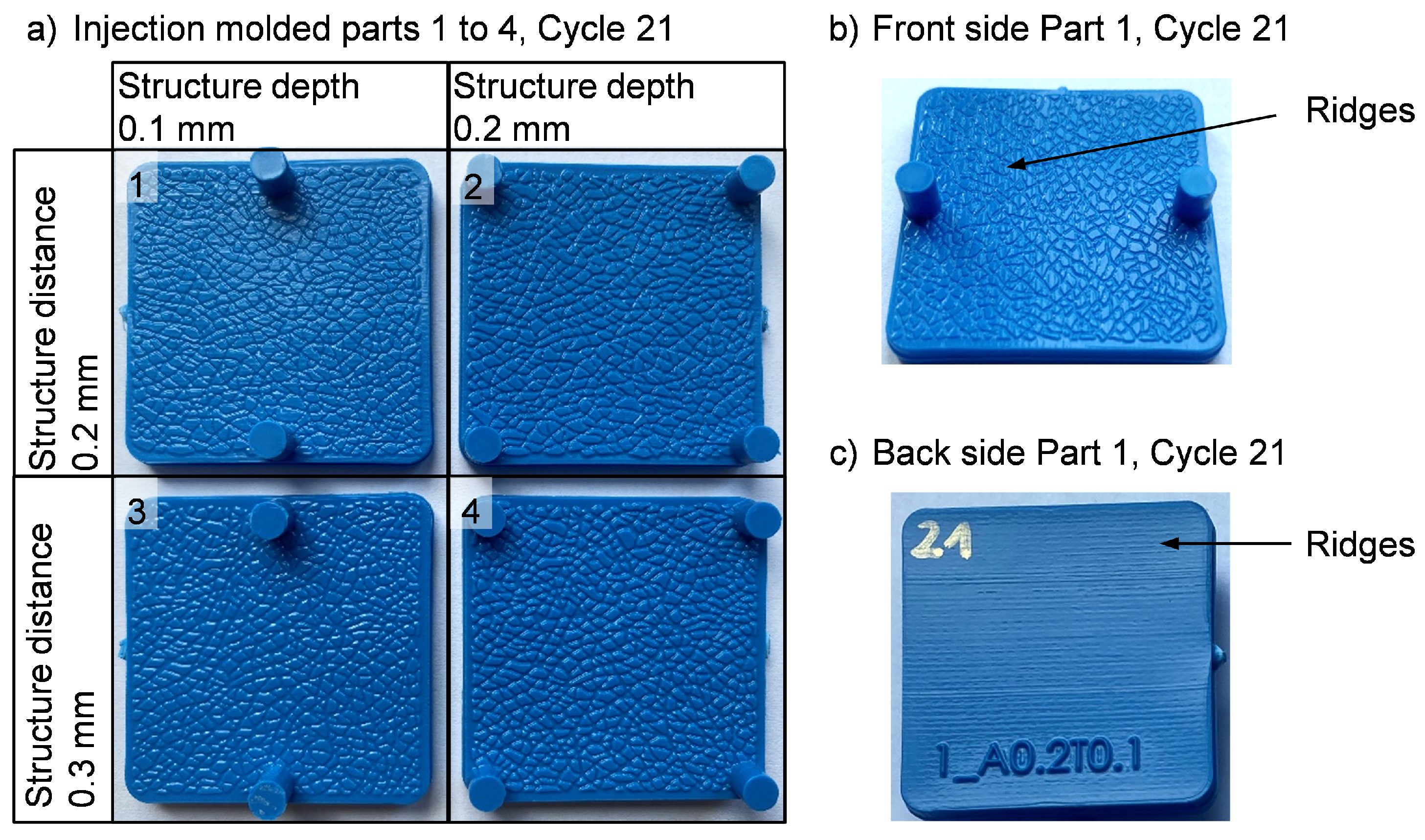
After performing a filling study of 20 cycles, ten parts were molded and then optically inspected. The injection molded parts show that the molding of the structure from the mold was successful. No flash has occurred and there are no voids, cavities or inclusions, see Figure 6a).
However, some ridges caused by the PolyJet™ production can be seen on the grain surface and the back side of the part, Figure 6b,c. The Ra and Rz values of the parts are shown in blue in Figure 5. The figure compares the molded parts with the respective mold cavity. The values from each cycle were determined and then averaged and the standard deviation determined.
The Ra values of parts 1–4 are in the same range as the Ra values of the respective mold cavity. In addition, the low standard deviation of the roughness measured in the parts shows that roughness only varies slightly between cycles. With regard to the Rz values, the situation is different for the parts and cavities 1 and 2. On average, the values are below those of the cavities. This deviation is not noticeable for the parts and cavities 3 and 4.
5. Discussion
The rounding of the edges in additive manufacturing, which was previously detected in the visual inspection, can be proven using quantitative data. This is caused by the liquid-based additive manufacturing technology by means of jetting. The photopolymer cannot be cured instantaneously so that the photopolymer is subjected to gravity before curing which results in less sharp contours. Ra values also show that the roughness values of cavities 1 and 3, as well as cavities 2 and 4, are in the same range. Therefore, changing the structure distance from 0.2 to 0.3 mm has no significant effect on the roughness for the printed cavities. With the different structure depths of 0.1 mm and 0.2 mm respectively, a difference in roughness values of 39–55 percent occurs. An analysis of the Rz values shows that in this experimental study, a lower structure depth is associated with greater deviations from the CAD mold. In relation to the Rz values, it is evident that all four structures are sufficient in depth to meet the CAD design. Based on the Ra values, a smoothing in cavity 3 and cavity 4 is also evident, but as the Rz values show, this occurs without loss of structure depth. For the final interpretation of the results, it can be deduced that the moulding takes place evenly in all cycles and that after 30 cycles the mold does not show any wear within the grain structure. This finding is supported by the comparison of injection mold roughness before and after use (Figure 4). However, the maximum roughness depths of the mold in cavity 1 and 2 are higher compared to the part. The parts from cavity 1 nevertheless achieve a sufficient structure depth and, taking into account the deviations, are closer to the specification of 0.1 mm than previously assumed by the mold measurements. The parts from all four cavities thus deviate only minimally from the respective specifications of 0.1 mm and 0.2 mm. Comparing Rz values of injection mold and parts reveals lower values for the parts. This may be caused by shrinkage which is a typical phenomenon for injection molded parts as well as their surfaces. It should be noted that an anti-reflective spray was also applied for the mold measurements, which may have an influence on the roughness measurements. In conclusion, it can be stated on the basis of the roughness measurements that both the reproducibility and a sufficient molding of the structures are given.
6. Conclusions
The aim of this study was to realize grained surfaces for prototype tools. Initially, the conventional manufacturing methods for grain structured molds were presented and additive manufacturing of molds was discussed. Subsequently, four different grain structures were designed on square parts using CAD. Based on this, a mold was designed for additive manufacturing and was manufactured using the PolyJet™ process. After microscopic analysis of the mold cavities, it was determined that it was feasible to manufacture typical grain structures using the PolyJet™ process. This was followed by injection molding tests with the additively manufactured mold to determine whether the grain structures could be molded. In this context, some ridges were visible on the part surface, which can occur in the manufacturing of the PolyJet™ mold due to the material application by means of nozzles. Furthermore, an anti-reflective spray was used for the mold measurements. The spray ensured that the ridges, which were low in comparison to the grain structure, were covered and no longer recorded by measurements. It should also be noted that the measurement of surface roughness is based on an average of five line-based measurements. Alternative measuring techniques for directly determining the surface roughness rather than a line-based roughness should be considered for future work. In conclusion, the primary aim of the work to produce an injection mold for grained part surfaces by polymer additive manufacturing can be considered fulfilled. Four grain structures with different parameters were produced equally successfully in the mold and were reproducible. Especially in comparison to the frequently used etching, this offers the possibility to reproduce grain structures and directly control their design. In the future, the feasibility could additionally be investigated on three-dimensional parts where the grain structure is provided on all sides of the part. The results show that small improvements are still possible for the desired quality of grained surfaces from additively manufactured molds. This conclusion relates above all to the PolyJet™ process, since the ridges are a result of the production process. In this respect, there is a need for further research to counteract these ridges as far as possible. However, providing the parts with a grain structure makes the ridges on the surface less obvious. Thus, a grain structure can be used to improve the surface ridges caused by PolyJet™ manufacturing.
Another possibility to realize grain structures in additively manufactured molds is to produce the molds using vat-based stereolithography (SLA). The process offers a high surface quality and could therefore be suitable for higher-quality graining in molds. Further trials using SLA-produced grained molds would therefore be beneficial.
Author Contributions
Conceptualization, J.A.A.; methodology, J.A.A. and A.D.; investigation, A.D.; resources, G.B. and P.B.; writing—original draft preparation, J.A.A. and A.D.; writing—review and editing, G.B.; funding acquisition, P.B. All authors have read and agreed to the published version of the manuscript.
Funding
This research as well as the article processing charge were funded by the German Federal Ministry for the Environment, Nature Conservation and Nuclear Safety (BMU), grant number 16EM3164-2.
Data Availability Statement
Data is contained within the article.
Conflicts of Interest
The authors declare no conflict of interest.
References
- Glokowo, K.; Mugele, P.; Zimmer, D. Neue Möglichkeiten Der Innenraumgestaltung. ATZ Extra. 2017. Available online: https://www.bertrandt.com/fileadmin/files/files/00_Unternehmen/03_Presse/Fachartikel/2017/2017-08-16_Fachartikel_ATZextra_Automatisiertes_Fahren_Innenraumgestaltung_Bertrandt.pdf (accessed on 19 April 2022).
- Blomeyer, D.; Schulte-Gehrmann, A.L. Oberflächeninnovation für das Interieur künftiger Fahrzeuge. ATZ. 2019. Available online: https://www.springerprofessional.de/oberflaecheninnovationen-fuer-das-interieur-kuenftiger-fahrzeuge/16750348 (accessed on 19 April 2022).
- Lachmayer, R.; Lippert, R.B. Entwicklungsmethodik für die Additive Fertigung; Springer: Berlin/Heidelberg, Germany, 2020. [Google Scholar] [CrossRef]
- Lake, M. Oberflächentechnik in der Kunststoffverarbeitung, 2nd ed.; Hanser-eLibrary: Munich, Germany, 2016. [Google Scholar]
- Günther, S.; Georg, B.; Gerret, L.; Josef, A.A. Feasibility and Process capability of polymer additive injection molds with slide technology. Procedia CIRP 2020, 93, 102–107. [Google Scholar] [CrossRef]
- Kuo, C.C.; You, Z.Y.; Wu, J.Y.; Huang, J.L. Development and application of a conformal cooling channel with easy removal and smooth surfaces. Int. J. Adv. Manuf. Technol. 2019, 102, 2029–2039. [Google Scholar] [CrossRef]
- Dizon, J.R.C.; Valino, A.D.; Souza, L.R.; Espera, A.H.; Chen, Q.; Advincula, R.C. 3D Printed Injection Molds Using Various 3D Printing Technologies. Mater. Sci. Forum 2020, 1005, 150–156. [Google Scholar] [CrossRef]
- Zhang, Y.; Pedersen, D.B.; Mischkot, M.; Calaon, M.; Baruffi, F.; Tosello, G. A Soft Tooling Process Chain for Injection Molding of a 3D Component with Micro Pillars. J. Vis. Exp. JoVE 2018. [Google Scholar] [CrossRef]
- Dempsey, D.; McDonald, S.; Masato, D.; Barry, C. Characterization of Stereolithography Printed Soft Tooling for Micro Injection Molding. Micromachines 2020, 11, 819. [Google Scholar] [CrossRef]
- Dangel, R. Spritzgießwerkzeuge für Einsteiger, 2nd ed.; Hanser: Munich, Germany, 2017. [Google Scholar]
- Deutsches Institut für Normung. Leder- Terminologie- Hauptdefinitionen für den Lederhandel. 2015. Available online: https://www.beuth.de/de/norm/din-en-15987/224357219 (accessed on 19 April 2022). [CrossRef]
- StandexEngravingMoldTech. Texturkatalog. 2021. Available online: https://upmold.com/wp-content/uploads/Data-center/Mold-Tech-texture.pdf (accessed on 19 April 2022).
- Upmold. Yick Sang Texture Technology Datasheet. 2021. Available online: https://upmold.com/wp-content/uploads/Data-center/Yicksang-Texture-fold.pdf (accessed on 19 April 2022).
- Verein Deutscher Ingenieure. Elektroerosive Bearbeitung: Begriffe, Verfahren, Anwendung. 1975. Available online: https://www.beuth.de/de/technische-regel/vdi-3400/542958 (accessed on 19 April 2022).
- Grote, K.H.; Bender, B.; Göhlich, D.; Dubbel, H. Taschenbuch für den Maschinenbau, 25th ed.; Springer Vieweg: Berlin, Germany, 2018. [Google Scholar] [CrossRef]
- Pruner, H.; Nesch, W. Spritzgießwerkzeuge Kompakt: Ein Praxisbuch für Einsteiger, 2nd ed.; Hanser: Munich, Germany, 2020. [Google Scholar] [CrossRef]
- Klocke, F.; König, W. Fertigungsverfahren 3: Abtragen, Generieren Lasermaterialbearbeitung, 4th ed.; Fertigungsverfahren; Springer: Berlin/Heidelberg, Germany, 2007; Volume 3. [Google Scholar] [CrossRef] [Green Version]
- Biermann, D.; Kahnis, P.; Kuttkatt, B. Mikrofräsen filigraner Strukturen in Formeinsätzen. MM MaschinenMarkt 2010, 5, 36–40. [Google Scholar]
- Kordt, J.M. Konturnahes Laserstrukturieren für Kunststoffspritzgießwerkzeuge. 2007. Available online: https://publications.rwth-aachen.de/record/51988/files/Kordt_Johannes.pdf (accessed on 19 April 2022).
- Ho, K.; Newman, S. State of the art electrical discharge machining (EDM). Int. J. Mach. Tools Manuf. 2003, 43, 1287–1300. [Google Scholar] [CrossRef]
- Mappes, T.; Worgull, M.; Heckele, M.; Mohr, J. Submicron polymer structures with X-ray lithography and hot embossing. Microsyst. Technol. 2008, 14, 1721–1725. [Google Scholar] [CrossRef]
- Schlussbericht zu BMBF-Projekt “Holo-Impact: Nanostrukturieren von Metalloberflächen Mittels Holografischer Prägevorlagen”. 2010. Available online: https://www.tib.eu/en/suchen/id/TIBKAT:667760091/ (accessed on 19 April 2022).
- Zhang, J.; Cui, T.; Ge, C.; Sui, Y.; Yang, H. Review of micro/nano machining by utilizing elliptical vibration cutting. Int. J. Mach. Tools Manuf. 2016, 106, 109–126. [Google Scholar] [CrossRef]
- Deutsches Institut für Normung. Benennungen, Definitionen und Kenngrößen der Oberflächenbeschaffenheit. 2010. Available online: https://www.beuth.de/de/norm/din-en-iso-4287/129356592 (accessed on 19 April 2022).
- Deutsches Institut für Normung. Ermittlung der Rauheitskenngrößen Ra, Rz, Rmax Mit Elektrischen Tastschnittgeräten: Begriffe Messbedingungen. 1990. Available online: https://www.beuth.de/de/norm/din-4768/1552484 (accessed on 19 April 2022).
Figure 1.
(a) Designed parts with grain structure, (b) Designed mold of the ejector side.

Figure 2.
Mold with grain structure produced by means of PolyJet™.

Figure 3.
Comparison between designed and printed cavity 1.

Figure 4.
Exemplary comparison of the roughness profiles of CAD and PolyJet™ mold in cavity 1.

Figure 5.
Ra and Rz values of CAD template and PolyJet™ mold.

Figure 6.
(a) Parts 1 to 4 of the 21st injection molding cycle, (b) Ridges within the grain structure on part 1, (c) Ridges on the back of part 1.
Figure 6.
(a) Parts 1 to 4 of the 21st injection molding cycle, (b) Ridges within the grain structure on part 1, (c) Ridges on the back of part 1.


Table 1.
Overview of the process variants for structuring injection molds.
| Structuring Method | Structure Size | Advantages | Disadvantages |
|---|---|---|---|
| Photoetching | ∼1 µm [19] | - low process costs - uniform roughness and mattness | - many complex manual process steps - not achievable for all materials - no exact reproducibility of structures |
| EDM | ∼5 µm [20] | - high dimensional and shape accuracy - production of sharp edges | - high costs due to complex manufacturing of electrodes - only for conductive materials |
| Laser structruing | ∼1 µm [21] | - easy transfer of any structural pattern | - for complex shapes laser focusing is more complicated |
| Explosive embossing | ∼1 µm [22] | - very fine structures can be realized - few working steps necessary | - structure cannot be transferred to complex shapes - structural template necessary |
| Micromilling | ∼ 5 µm [23] | - high geometrical freedom - high removal rate | - increase in complexity due to miniaturization - high costs and machine running times |
Table 2.
Structural distances and depths of graining 1–4.
| Structure Distance [mm] | Structure Depth [mm] | |
|---|---|---|
| Graining 1 | 0.2 | 0.1 |
| Graining 2 | 0.2 | 0.2 |
| Graining 3 | 0.3 | 0.1 |
| Graining 4 | 0.3 | 0.2 |
Publisher’s Note: MDPI stays neutral with regard to jurisdictional claims in published maps and institutional affiliations. |
© 2022 by the authors. Licensee MDPI, Basel, Switzerland. This article is an open access article distributed under the terms and conditions of the Creative Commons Attribution (CC BY) license (https://creativecommons.org/licenses/by/4.0/).
Share and Cite
MDPI and ACS Style
Burggräf, P.; Bergweiler, G.; Abrams, J.A.; Dunst, A. Additive Surface Graining in Prototype Tooling for Injection Molding. J. Manuf. Mater. Process. 2022, 6, 54. https://doi.org/10.3390/jmmp6030054
AMA Style
Burggräf P, Bergweiler G, Abrams JA, Dunst A. Additive Surface Graining in Prototype Tooling for Injection Molding. Journal of Manufacturing and Materials Processing. 2022; 6(3):54. https://doi.org/10.3390/jmmp6030054
Chicago/Turabian StyleBurggräf, Peter, Georg Bergweiler, Josef Andrew Abrams, and Anna Dunst. 2022. "Additive Surface Graining in Prototype Tooling for Injection Molding" Journal of Manufacturing and Materials Processing 6, no. 3: 54. https://doi.org/10.3390/jmmp6030054