

Introduction: IOT Made Simple: Playing With the ESP32 on Arduino IDE


Let's explore in this tutorial, the ESP32, the fantastic newer Development Kit board for IoT use. This board, developed by Espressif, should be the NodeMCU's successor, due to its low price and great features.
But is also important to point that NOT ALL libraries or functions that you are used to working with ESP8266 and/or Arduino are yet functional on this new board. Probably this will be soon, so check it regularly on ESP 32 Forum WebPage.
Here we will learn how to program the ESP32 on Arduino IDE, exploring its most common functions and libraries, point some of the important differences and new features introduced with this great chip.
In short, we will explore:
- Digital Output: Blinking a LED
- Digital Input: Reading a Touch Sensor
- Analog Input: Reading a variable voltage from a potentiometer
- Analog Output: Controlling a LED brightness
- Analog Output: Controlling a Servo Position
- Reading Temperature/Humidity Data with a Digital sensor
- Connecting to the Internet and getting local time
- Receiving data from a simple local web page, turning on/off a LED
- Transmitting data to a simple local webPage
Step 1: The ESP32 Main Characterictics

The ESP32 is an under US$10 board with great advantages over similar IoT boards in the market.
This board has a dual processed microprocessor that helps a lot, because when one processor is handle communication, the other one is in charge of I/O control, for example. This feature will prevent some issues that happen with ESP8266, where the sole CPU needs stop controlling I/Os when handle with Comm. Besides, the ESP32 has integrated WIFI, BLUETOOTH, DAC, several ADC (not only one as the ESP8266), capacitive touch sensors, etc (give a look at above block diagram). And the good news is that Power Consumption is almost the same as ESP8266.
Bellow a chart that can show us its main characteristics, and differences when compared with ESP8266:
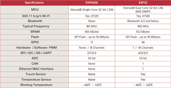
Let's point its main properties in more details:
Key Features:
- 240 MHz dual core Tensilica LX6 microcontroller with 600 DMIPS
- Integrated 520 KB SRAM
- Integrated 802.11 b/g/n HT40 Wi-Fi transceiver, baseband, stack and LwIP
- Integrated dual mode Bluetooth (classic and BLE)
- 16 MB flash, memory-mapped to the CPU code space
- 2.3V to 3.6V operating voltage
- -40°C to +125°C operating temperature
- Onboard PCB antenna / IPEX connector for external antenna
Sensors:
- Ultra-low noise analog amplifier
- Hall sensor
- 10x capacitive touch interfaces
- 32 kHz crystal oscillator
34 x GPIO:
- 3 x UARTs, including hardware flow control
- 3 x SPI
- 2 x I2S
- 18 x ADC input channels
- 2 x DAC
- 2 x I2C
- PWM/timer input/output available on every GPIO pin
- OpenOCD debug interface with 32 kB TRAX buffer
- SDIO master/slave 50 MHz
- Supports external SPI flash up to 16 MB
- SD-card interface support
Security Related:
- WEP, WPA/WPA2 PSK/Enterprise
- Hardware accelerated encryption: AES/SHA2/Elliptical Curve Cryptography/RSA-4096
Performance:
- Supports sniffer, Station, SoftAP and Wi-Fi direct mode
- Max data rate of 150 Mbps@11n HT40, 72 Mbps@11n HT20, 54 Mbps@11g, and 11 Mbps@11b
- Maximum transmit power of 19.5 dBm@11b, 16.5 dBm@11g, 15.5 dBm@11n
- Minimum receiver sensitivity of -97 dBm
- 135 Mbps UDP sustained throughput
- 5 μA power consumption in Deep-sleep
Step 2: BoM - Bill of Material
- ESP32 Dev Kit: ESP32 Development Board (US$ 8.52)
- Micro Servo: TowerPro SG90 9G Mini Servo (US$ 3.80)
- Temp/Hum Sensor DHT22/AM2302 Digital Temperature and Humidity Sensor (US$ 9.99)
- LED
- 2 x Resistors: 330 ohm and 10K ohm
- Potentiometer: 10K ohm
- Protoboards
Step 3: ESP32 Arduino IDE Installation
We will use the Arduino IDE to program our ESP32, same way we do with the ESP8266 family.
Install Drivers:
It is important that you have installed on your computer, the updated CP210x USB to UART Driver. Enter in this link: usb-to-uart-bridge-vcp-drivers and install the proper driver for your OS.
Install Library:
The novelty here is that Expressif itself in its GitHub, will give us the proper directions for library installation: arduino-esp32. Follow the instructions for your OS. In my case (MacOS), the installation is very simple:
Open Terminal and execute the following command (copy->paste and hit enter):
mkdir -p ~/Documents/Arduino/hardware/espressif && \
cd ~/Documents/Arduino/hardware/espressif && \
git clone https://github.com/espressif/arduino-esp32.git esp32 && \
cd esp32/tools/ && \
python get.py
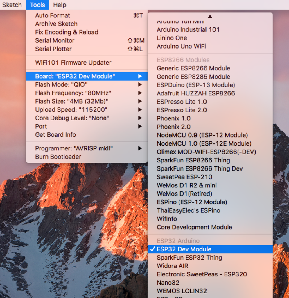
After that, restart Arduino IDE and it's done! You must see several boards on "TOOLS" Menu. Select the appropriate for you. In general, the "generic" ESP32 DEV MODULE works fine.
When you open the Arduino IDE for the first time, you will note that the default upload speed is 921,600 bauds. This can provoque instability. Change it to 115,200 bauds!
Step 4: Hello World! Blinking a LED
As usual, the first thing to do when we start exploring a new HW is to blink a LED.
Go to Examples Menu in the IDE and open the Blink sketch.
The ESP32 DevKit, has a built-in LED that is connected to its GPIO 02. It is important to check if "LED_BUILTIN" is automatically recognized by IDE. If not, you must add to code the line:
int LED_BUILTIN = 2;
Each ESP32 board has an internal LED connected to a different GPIO
/*
  ESP 32 Blink
  Turns on an LED on for one second, then off for one second, repeatedly.
  The ESP32 has an internal blue LED at D2 (GPIO 02)
*/

int LED_BUILTIN = 2;

void setup()
{
  pinMode(LED_BUILTIN, OUTPUT);
}

void loop()
{
  digitalWrite(LED_BUILTIN, HIGH);   // turn the LED on (HIGH is the voltage level)
  delay(1000);                       // wait for a second
  digitalWrite(LED_BUILTIN, LOW);    // turn the LED off by making the voltage LOW
  delay(1000);                       // wait for a second
}
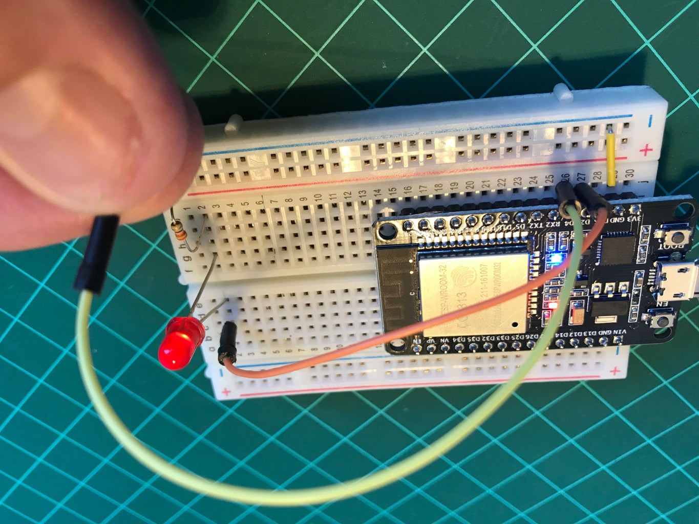
Below the internal LED blinking (note the blue light) together with an external one connected to GPIO 2:
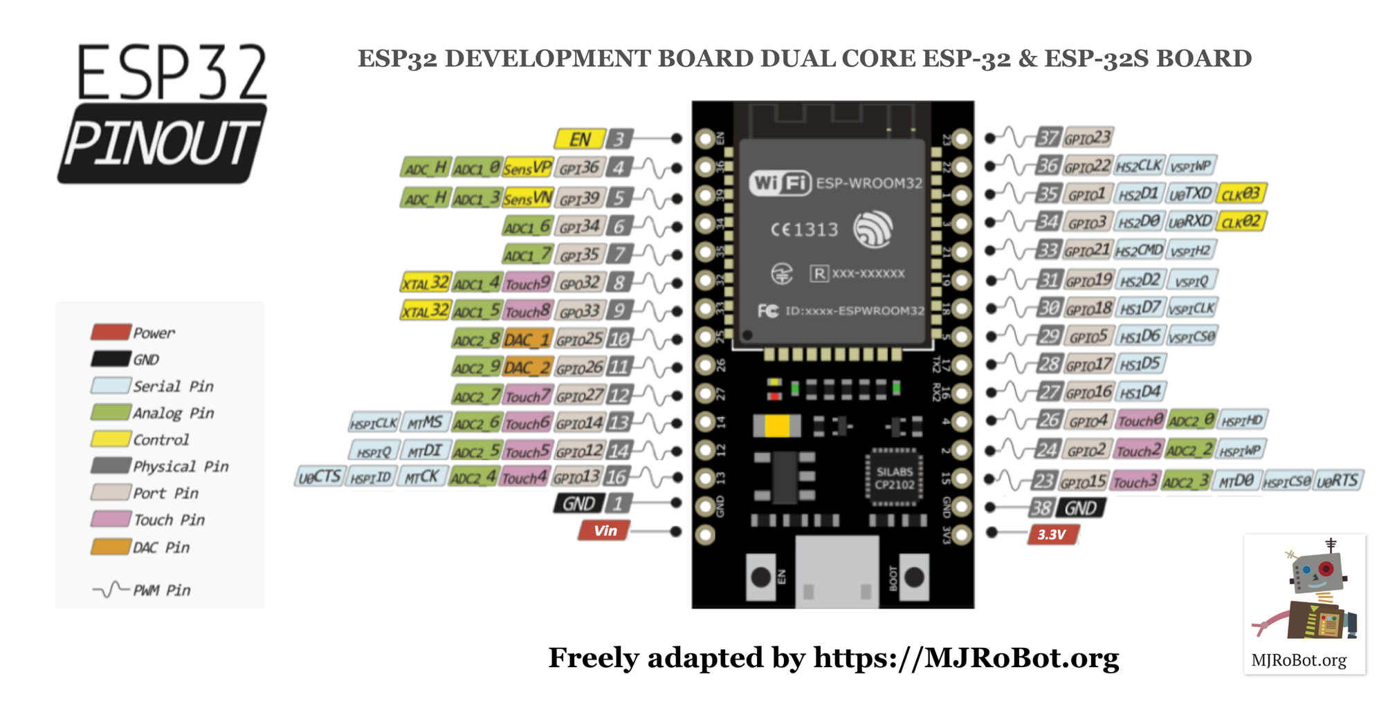
There are several different boards with different pin maps in the market. The above diagram shows the board that I am using. You can find it here: /ESP32-Development-Board
Perfect! So, DigitalWrite() is working perfectly, same way with ESP8266 and Arduino. BTW, DigitalRead() also works the same way to read a digital input, like a push-button for example.
Step 5: The Touch Sensor
Let's jump to a new cool feature, the Touch Sensor!
The ESP32 has 10 internal capacitive touch sensors. You can use it as buttons for example.
Those sensors are connected with several GPIOs:
- T0: GPIO 4
- T1: GPIO 0
- T2: GPIO 2
- T3: GPIO 15
- T4: GPIO 13
- T5: GPIO 12
- T6: GPIO 14
- T7: GPIO 27
- T8: GPIO 33
- T9: GPIO 32
In order to read them you must use the function: touchRead(Touch Pin #);
For example, to read the Touch Sensor 0 (T0), you must do something like:
int value = touchRead(4);
Let's create a code, where if we touch the sensor T0 (GPIO4), the LED will be on.
Use the serial monitor to check the values read by the sensor and adjust the code properly.
Below the complete code:
/*****************************************************
* ESP32 Touch Test and LED Ctrl
* Touch pin ==> Touch0 is T0 which is on GPIO 4 (D4).
* LED pin   ==> D2
*
* MJRoBot.org 6Sept17
*****************************************************/

#define TOUTCH_PIN T0 // ESP32 Pin D4
#define LED_PIN 2
int touch_value = 100;

void setup()
{
  Serial.begin(115200);
  delay(1000); // give me time to bring up serial monitor
  Serial.println("ESP32 Touch Test");
  pinMode(LED_PIN, OUTPUT);
  digitalWrite (LED_PIN, LOW);
}

void loop()
{
  touch_value = touchRead(TOUTCH_PIN);
  Serial.println(touch_value);  // get value using T0
  if (touch_value < 50)
  {
    digitalWrite (LED_PIN, HIGH);
  }
  else
  {
    digitalWrite (LED_PIN, LOW);
  }
  delay(1000);
}
And below the ESP32 working:
Step 6: Analog Input


Let's now test how to Input analog value signals.
There are in total 18 x 12 bits ADC input channels, versus only 1 X 10bits ADC on NodeMCU.
GPIO ADC Channel
- GPIO 0 ==> ADC2_CH1
- GPIO 2 ==> ADC2_CH2
- GPIO 4 ==> ADC2_CH0
- GPIO 12 => ADC2_CH5
- GPIO 13 => ADC2_CH4
- GPIO 14 => ADC2_CH6
- GPIO 15 => ADC2_CH3
- GPIO 25 => ADC2_CH8
- GPIO 26 => ADC2_CH9
- GPIO 27 => ADC2_CH7
- GPIO 32 => ADC1_CH4
- GPIO 33 => ADC1_CH5
- GPIO 34 => ADC1_CH6
- GPIO 35 => ADC1_CH7
- GPIO 36 => ADC1_CH0
- GPIO 37 => ADC1_CH1
- GPIO 38 => ADC1_CH2
- GPIO 39 => ADC1_CH3
To read the analog input, you will the same as have done with Arduino and ESP8266:
int analog_value = analogRead(36);
It's very important to note that, the ESP32 ADCs have 12bits of resolution (versus 10bits on ESP8266 and Arduino), so the total range of ADCs reading go to 4,095 (instead 1,027 on Arduinos and ESP8266) when a maximum of 3.3V is applied to its inputs.
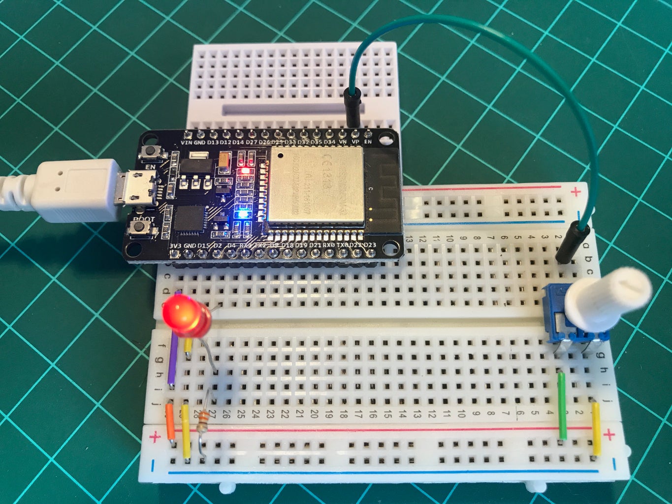
For input, let's use a 10K ohm potentiometer, connecting it from 3.3V and GND. Let's use its variable output to be the input for ESP32 ADC pins. The Above diagram shows the potentiometer connected to GPIO 36 that is the ADC1 Channel 0. Try also other inputs on your board.
Run the simple code below:
/******************************************************
* ESP32 Analog Input Test
* Analog Input: ADC_1_0 pin ==> GPIO36 (VP).
*
* MJRoBot.org 6Sept17
*****************************************************/
//Analog Input
#define ANALOG_PIN_0 36
int analog_value = 0;

void setup()
{
  Serial.begin(115200);
  delay(1000); // give me time to bring up serial monitor
  Serial.println("ESP32 Analog IN Test");
}

void loop()
{
  analog_value = analogRead(ANALOG_PIN_0);
  Serial.println(analog_value);
  delay(500);
}
Turn your potentiometer and observe on IDE Serial Monitor the measurements going from zero to 4,095.
Step 7: Dimming a LED: Analog Output Using PWM
If we want to "Dimmer a LED" on ESP8266 or an Arduino, we can simply use a command like analogWrite(), that will vary the PWM value of its output, simulating an analog value. Unfortunately, we still do not have such kind of command developed for the ESP32 on Arduino IDE. but the very good news is that all 36 of ESP32 GPIOs has a PWM capability, what is great! Only we must use more complex code to reach the same result.
So, let's program one of that GPIOs with a PWM output signal.
You can find a very good tutorial in details about how PWM works at this link: esp32-arduino-led-pwm-fading.
The first thing to think about a PWM signal to be generated is its frequency. We will use a value of 5000 Hz, that works fine with the LED. We must also specify the LED PWM channel and the resolution of the PWM duty cycle, in bits. We can choose a channel from 0 to 15 and a resolution between 1 and 16 bits. We will use channel 0 and a resolution of 8 bits.
int freq = 5000;
int ledChannel = 0;
int resolution = 8;
Let's use GPIO2, where we have our external LED attached (and the internal one).
#define LED_PIN 2
Those parameters must be defined during setup() phase, using below functions:
void setup()
{
  ledcSetup(ledChannel, freq, resolution);
  ledcAttachPin(LED_PIN, ledChannel);
}
To turn on the LED with a specific brightness, we must define the "duty cycle".
For example, to turn off the LED, the duty cycle must be zero and the function ledcWrite(ledChannel, dutyCycle) used to send the value thru a specific PWM channel:
int dutyCycle = 0;
ledcWrite(ledChannel, dutyCycle);
Different values of the dutyCycle variable will turn on the LED with different brightness. this variable, dutyCycle, will vary from 0 to 255, once the resolution used is 8 bits.
We can use the Potentiometer (connected to analog_value variable) to manually setup the dutyCycle variable, but once their range of values are different, let's use a map function to match input and output:
dutyCycle = map(analog_value, 0, 4095, 0, 255);
Below the complete code:
*****************************************************
* ESP32 Analog Input/Output Test
* Analog Input: ADC_1_0 pin ==> GPIO36 (VP).
* PWM LED pin   ==> GPIO 02
*
* MJRoBot.org 6Sept17
*****************************************************/
//Analog Input
#define ANALOG_PIN_0 36
int analog_value = 0;

// PMW LED
#define LED_PIN 2
int freq = 5000;
int ledChannel = 0;
int resolution = 8;
int dutyCycle = 0;

void setup()
{
  Serial.begin(115200);
  delay(1000); // give me time to bring up serial monitor
  Serial.println("ESP32 Analog IN/OUT Test");

  ledcSetup(ledChannel, freq, resolution);
  ledcAttachPin(LED_PIN, ledChannel);
  ledcWrite(ledChannel, dutyCycle);
}

void loop()
{
  analog_value = analogRead(ANALOG_PIN_0);
  Serial.println(analog_value);
  dutyCycle = map(analog_value, 0, 4095, 0, 255);
  ledcWrite(ledChannel, dutyCycle);
  delay(500);
}
That's it!
Step 8: Servo Control


Let's control a Servo Motor using the PWM capability of our ESP32. The code will be basically the same one that was used to control the LED brightness.
First, it's important to remember that the frequency to work with a Micro Servo is 50Hz, so we must change the frequency parameter to 50 (instead of 5,000 used with LED). We must also specify the LED PWM channel and the resolution of the PWM duty cycle, in bits. We will use again channel 0 and a resolution of 8 bits.
int freq = 50;
int channel = 0;
int resolution = 8;
The Servo will be connected to GPIO 5 (see above electrical diagram).
#define SERVO_PIN 5
Same as with LED, those parameters must be defined during setup() phase, using below functions:
void setup()
{
  ledcSetup(channel, freq, resolution);
  ledcAttachPin(SERVO_PIN, channel);
}
To position the servo on a specific angle, we must define the "duty cycle" (please, see the above diagram).
For example, to position the servo around 90 degrees, the duty cycle must be around 21 and the function ledcWrite(ledChannel, dutyCycle) should be used to send the value thru the PWM channel:
int dutyCycle = 21;
ledcWrite(channel, dutyCycle);
Different values of the dutyCycle variable will position the servo with different angles. This variable, dutyCycle, should vary from 10 to 32 (this range was gotten manually).
Same as we did with the LED, the Potentiometer (connected to analog_value variable) can be used to manually setup the dutyCycle variable and so, changing the servo position. Once their ranges of values are different, let's use a map function to match input and output:
dutyCycle = map(analog_value, 0, 4095, 10, 33);
Below the complete code:
/*****************************************************
* ESP32 Servo Control
* Analog Input: ADC_1_0 pin ==> GPIO36 (VP).
* PWM SERVO pin   ==> GPIO 05
*
* MJRoBot.org 6Sept17
*****************************************************/
//Analog Input
#define ANALOG_PIN_0 36
int analog_value = 0;

// PMW SERVO
#define SERVO_PIN 5
int freq = 50;
int channel = 0;
int resolution = 8;
int dutyCycle = 21;

void setup()
{
  Serial.begin(115200);
  delay(1000); // give me time to bring up serial monitor
  Serial.println("ESP32 Servo Control");

  ledcSetup(channel, freq, resolution);
  ledcAttachPin(SERVO_PIN, channel);
  ledcWrite(channel, dutyCycle);
}

void loop()
{
  analog_value = analogRead(ANALOG_PIN_0);
  Serial.print(analog_value);
  Serial.print(" Duty Cycle ==> ");
  Serial.println(dutyCycle);
  dutyCycle = map(analog_value, 0, 4095, 10, 33);
  ledcWrite(channel, dutyCycle);
  delay(50);
}
Now we can work with the Ultrasonic Sensor on top of the servo and build an IoT Radar!. But this will be another tutorial! ;-)
Step 9: Connecting to Internet: Local Time Stamp

After testing some of the GPIO digital/analog and input/output capabilities, let's connect our ESP32 on the internet!
With ESP8266 family we were using the library esp8266wifi.h for that. With the ESP32, the library to use will be:
<wifi.h>
A very simple example would be programming our board to capture from the internet the local time. This is a very good feature to have on hand on projects. The below code will do it for us:
/**************************************************************
 * Local Time Stamp with ESP32
 * Developed by Marcelo Rovai - 8 September 2017
 **************************************************************/
#include <NTPClient.h>
#include <WiFi.h>
#include <WiFiUdp.h>

#define NTP_OFFSET  -3  * 60 * 60 // In seconds
#define NTP_INTERVAL 60 * 1000    // In miliseconds
#define NTP_ADDRESS  "europe.pool.ntp.org"

WiFiUDP ntpUDP;
NTPClient timeClient(ntpUDP, NTP_ADDRESS, NTP_OFFSET, NTP_INTERVAL);

void setup()
{
  Serial.begin(115200);
  timeClient.begin();
}
You can see at Serial monitor the local time being stamped.
Step 10: Simple WiFi Server

Let's now test our ESP32 as a simple WiFi Server.
- Open the EXAMPLES menu on your Arduino IDE and get the ESP32 WiFi/SimpleWiFiServer.ino sketch:
About this program:
WiFi Web Server LED Blink
- Created for arduino 25 Nov 2012 by Tom Igoe
- Ported for sparkfun esp32 31.01.2017 by Jan Hendrik Berlin
A simple web server that lets you blink an LED via the web. This sketch will print the IP address of your ESP32 WiFi network to the Serial monitor. From there, you can open that address in a web browser to turn on and off the LED on pin 5.
If the IP address of your board is for example 10.0.1.40:
- http://10.0.1.40/Hturns the LED on
turns the LED off
This example is written for a network using WPA encryption. For WEP or WPA, change the Wifi.begin() call accordingly.
Circuit: LED attached to pin 5
So, let's use the program without significant modifications. Change the External LED Pin to GPIO5
Off course, if you prefer change the code for GPIO2 w/o changing the HW.
First, enter your network credentials:
const char* ssid     = "yourssid";
const char* password = "yourpasswd";
And upload it on your ESP32.
The first thing that you will see at your serial Monitor will be the information that your ESP32 is connected and what is its Ip Address:
WiFi connected.
IP address:
10.0.1.40
Open your favorite browser, typing this IP address. You will get a WebPage like the one above. There you can Turn on or off the LED remotely.
Step 11: DHT 22 - Reading Temperature and Humidity


A very useful sensor to be used on IoT projects is the DHT 11 or 22. They are very cheap and easy to include in your projects.
First, you need to have the Adafrut Library installed on your IDE. Go to their GitHub and download the updated version of this library: DHT-sensor-library
Unzip the file, rename it to DHT and move the complete folder to your Arduino Library directory
When I used for the first time I got a message:
fatal error: Adafruit_Sensor.h: No such file or directory
After some digging, I found that it is also necessary to have the Adafruit Unified Sensor Library also installed. So, I did it from Arduino IDE Library Manager (see picture above). After that, everything worked fine, same as we use to do with Arduino and NodeMCU.
Let's do some tests with this sensor. Follow the above electrical diagram and install the DHT22 as shown (looking the sensor with the "grid" face you, count the 4 legs from left to right):
- Pin VCC ==> 3.3V
- Pin Data ==> GPIO 23
- N/C
- PIN GND ==> GND
Also, connect a 10K ohm resistor between VCC and Data.
That's it!
You can use the "DHT tester.ino" example sketch that it is included in the library, or do your own.
I wrote a simple code for test the sensor as shown below:
/*****************************************************
* ESP32 DHT Reading
* DHT Input: ==> GPIO23.
*
* MJRoBot.org 9Sept17
*****************************************************/

/* DHT */
#include "DHT.h"
#define DHTPIN 23
#define DHTTYPE DHT22
DHT dht(DHTPIN, DHTTYPE);
float localHum = 0;
float localTemp = 0;

void setup()
{
  Serial.begin(115200);
  delay(1000); // give me time to bring up serial monitor
  Serial.println("");
  Serial.println("ESP32 DHT Temperature and Humidity ");
  Serial.println("");
  dht.begin();
}

void loop()
{
  getDHT();
  Serial.print("Temp: ==> ");
  Serial.print(localTemp);
  Serial.print("  Hum ==> ");
  Serial.println(localHum);
  delay(2000);
}

/***************************************************
* Get indoor Temp/Hum data
****************************************************/
void getDHT()
{
  float tempIni = localTemp;
  float humIni = localHum;
  localTemp = dht.readTemperature();
  localHum = dht.readHumidity();
  if (isnan(localHum) || isnan(localTemp))   // Check if any reads failed and exit early (to try again).
  {
    localTemp = tempIni;
    localHum = humIni;
    return;
  }
}
You can see the result on above PrintScreen of Serial Monitor.
Step 12: Sending and Receiving Data From a Local Web Page


Reviewing what we covered so far in this tutorial:
- Digital Output: Blinking a LED
- Digital Input: Reading a Touch Sensor
- Analog Input: Reading a variable voltage from a potentiometer
- Analog Output: Controlling a LED brightness
- Analog Output: Controlling a Servo Position
- Reading Temperature/Humidity Data with a Digital sensor
- Connecting to the Internet and getting local time
- Creating a simple web page to turn on/off a LED (receiving data)
We realize that we still must try to send data to a web page. So, let's do it!
We will take the data generated from our DHT sensor and the analog value provided by the potentiometer and send them to the web page created to control the LEDs.
I started from the SimpleWiFiServer code used in step 10 and added the pertinent lines of code to get the potentiometer and DHT data.
Note that I moved back the LED to GPIO 2 as you could see on the electrical diagram.
Download the complete code from my GitHub: ESP32_WiFi_Server_Sending_Receiving_Data.ino
Note that I organized the code better and now, the loop() is only:
void loop()
{
  analog_value = analogRead(ANALOG_PIN_0);
  getDHT();
  WiFiLocalWebPageCtrl();
}
The novelty here is the "WiFiLocalWebPageCtrl()" function. But, this is exactly the original setup() function used on SimpleWebServer. What I included inside this function, is what should appear in the web page (see the above print screen for the web page).
// the content of the HTTP response follows the header:
            //WiFiLocalWebPageCtrl();
              client.print("Temperature now is: ");
              client.print(localTemp);
              client.print("  oC<br>");
              client.print("Humidity now is:     ");
              client.print(localHum);
              client.print(" % <br>");
              client.print("<br>");
              client.print("Analog Data:     ");
              client.print(analog_value);
              client.print("<br>");
              client.print("<br>");

              client.print("Click <a href=\"/H\">here</a> to turn the LED on.<br>");
              client.print("Click <a href=\"/L\">here</a> to turn the LED off.<br>");
Note that the temperature, humidity and analog values, will be updated everytime that you click on the links used to LED control or when you refresh the page.
Step 13: Conclusion

We could go on and on here, but we would never covered all ESP32 functions or potentiality. There is a lot left to explore with this great IoT device and on my next tutorial, you will learn how to add an OLED display on your ESP32:
ESP32 and OLED Display: Internet Clock - DHT22
We will return soon with new ESP32 tutorials!
As always, I hope this project can help others find their way in the exciting world of electronics, robotics, and IoT!
Please visit my GitHub for updated files: Playing with ESP32 and Arduino IDE
For more projects, please visit my blog: MJRoBot.org
Saludos from the south of the world!
See you at my next instructable!
Thank you,
Marcelo

Participated in the
Automation Contest 2017

Participated in the
GIFs Challenge 2017


