BCI Medical
8400 Capnocheck Service Manual Ver 6 Dec 2002
Service Manual
59 Pages
Preview
Page 1
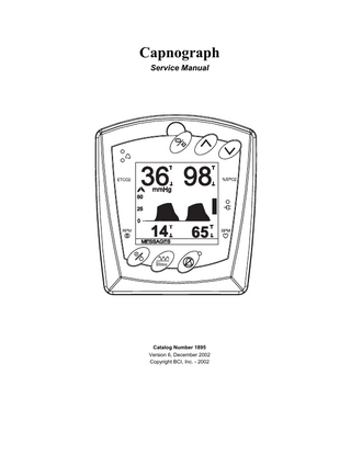
Capnograph Service Manual
Catalog Number 1895 Version 6, December 2002 Copyright BCI, Inc. - 2002
Table of Contents
CAPNOGRAPH SERVICE MANUAL Proprietary Notice... iv WARRANTY ... iv Limited Warranty ... iv Disclaimer of Warranties ... iv Conditions of Warranty... v Limitation of Remedies... v Warranty Procedure ... v CE Notice... v
Chapter 1: Introduction
1-1
Intended Use: ...1-1 Symbol Definitions ...1-1 2 Warnings, Cautions, and Notes...1-2 Warnings ...1-2 Cautions ...1-3 Notes ...1-4
Chapter 2: Product Description
2-1
20652B1 Main Processor Board ...2-2 Power Supplies ...2-3 Microprocessor and Memory ...2-3 External Timer Circuitry ...2-3 Printer Interface...2-4 Front Panel Interface...2-4 COMET CO2 Sensor (Bench) ...2-4 Analog Acquisition Circuitry...2-4 Display Interface ...2-5 Speaker Drive Circuitry ...2-5 Pump Control ...2-6 Valve Control...2-6 Serial interface ...2-6
Chapter 3: Pulse Oximetry
3-1
Product Description ...3-1 Theory of Operation...3-1 Product Specifications ...3-2 Data Provided to the Host System ...3-2 Data Provided From the Host System (Protocol #1 and Protocol #2)...3-2 Data Provided From the Host System (Protocol #3)...3-2 Power Requirements ...3-2 Dimensions...3-2 Serial Communications Specifications ...3-3 Communication Protocols ...3-3 Communication Protocol #1 ...3-3 Communication Protocol #2 ...3-3 Communication Protocol #3 ...3-3
Capnograph Service Manual
i
Table of Contents
Serial Communication Notes - Protocol #1 and Protocol #2 ... 3-4 Oximeter Transmitted Data – Protocol #1 ... 3-5 Oximeter Transmitted Data – Protocol #2 ... 3-6 Oximeter Received Data – Protocol #1 and Protocol #2 ... 3-7 Serial Communication Notes – Protocol #3... 3-7 Slow Data Packet Format ... 3-7 Slow Data Message Format ... 3-8 Fast Data Message Format... 3-9 Pin Description ... 3-10 Jumper Settings... 3-11 Probes ... 3-12 Checking Pulse Oximeter Performance ... 3-12 Demonstration Software ... 3-13
Chapter 4: C02 Theory of Operation
4-1
Theory of Operation ... 4-1 Measuring CO2 ... 4-1 Measuring Respiration Rate... 4-2 N2O Compensation ... 4-2
Chapter 5: Pneumatics and CO2 Calibration
5-1
Connecting a Non-Recirculating Scavenging System ... 5-1 Checking for Leaks... 5-2 Calibrating the Capnograph... 5-2 Low Calibration ... 5-2 Low/High Calibration ... 5-3
Chapter 6: Printer Output
6-1
Printer Setup ... 6-1 Printer Menu ... 6-2 Printer/Output ... 6-3 Output Examples: ... 6-5 Patient Data... 6-5 Trend Table Data ... 6-5
Chapter 7: Routine Maintenance
7-1
Charging the Battery... 7-1 Cleaning and Disinfecting ... 7-1 Maintenance Chart... 7-2 Long Term Storage ... 7-2 General Cleaning ... 7-3 Performance and Safety Checks ... 7-3 Inspecting the System ... 7-3 Cables and Cords ... 7-3
Chapter 8: Troubleshooting
8-1
Troubleshooting the Occlusion Low Priority Alarm ... 8-2
ii
Capnograph Service Manual
Table of Contents
Chapter 9: Supplies, Accessories & Specifications
9-1
Supplies and Accessories...9-1 Ordering Information ...9-2 Specifications...9-3 Capnograph ...9-3 Respiration Rate ...9-3 SpO2 ...9-3 Peripheral Pulse Rate ...9-4 Pulse Strength ...9-4 Alarm Limits Ranges ...9-4 Serial Output ...9-5 Power ...9-5 Physical ...9-5 Environment...9-5
Appendix: Parts Lists, Assembly Drawings
Capnograph Service Manual
Appendix-1
iii
Proprietary Notice
Proprietary Notice Information contained in this document is copyrighted by BCI, Inc. and may not be duplicated in full or part by any person without prior written approval of BCI, Inc. Its purpose is to provide the user with adequately detailed documentation to efficiently install, operate, maintain, and order spare parts for the device supplied. Every effort has been made to keep the information contained in this document current and accurate as of the date of publication or revision. However, no guarantee is given or implied that the document is error free or that it is accurate with regard to any specification.
WARRANTY Limited Warranty Seller warrants to the original purchaser that the Product, not including accessories, shall be free from defects in materials and workmanship under normal use, if used in accordance with its labeling for two years from the date of shipment to the original purchaser. Seller warrants to the original purchaser that the reusable oximeter sensors supplied as accessories, shall be free from defects in materials and workmanship under normal use, if used in accordance with its labeling for one year from the date of shipment to the original purchaser (USA ). Disclaimer of Warranties THE FOREGOING EXPRESS WARRANTY, AS CONDITIONED AND LIMITED, IS IN LIEU OF AND EXCLUDES ALL OTHER WARRANTIES WHETHER EXPRESS OR IMPLIED, BY OPERATION OF LAW OR OTHERWISE, INCLUDING BUT NOT LIMITED TO, ANY IMPLIED WARRANTIES OF MERCHANTABILITY OR FITNESS FOR A PARTICULAR PURPOSE. Seller disclaims responsibility for the suitability of the Product for any particular medical treatment or for any medical complications resulting from the use of the Product. This disclaimer is dictated by the many elements which are beyond Seller’s control, such as diagnosis of patient, conditions under which the Product may be used, handling of the Product after it leaves Seller’s possession, execution of recommended instructions for use and others.
iv
Capnograph Service Manual
CE Notice
Conditions of Warranty This warranty is void if the Product has been altered, misused, damaged by neglect or accident, not properly maintained or recharged, or repaired by persons not authorized by Seller. Misuse includes, but is not limited to, use not in compliance with the labeling or use with accessories not manufactured by Seller. This warranty does not cover normal wear and tear and maintenance items. Limitation of Remedies The original purchaser’s exclusive remedy shall be, at Seller’s sole option, the repair or replacement of the Product. THIS IS THE EXCLUSIVE REMEDY. In no event will Seller’s liability arising out of any cause whatsoever (whether such cause is based in contract, negligence, strict liability, tort or otherwise) exceed the price of the Product and in no event shall Seller be responsible for consequential, incidental or special damages of any kind or nature whatsoever, including but not limited to, lost business, revenues and profits. Warranty Procedure To obtain warranty service in the USA, you must request a Customer Service Report (CSR) number from Technical Service. Reference the CSR number when returning your Product, freight and insurance prepaid, to: BCI, Inc., N7 W22025 Johnson Road, Waukesha, WI 53186-1856. Telephone: 1-800-558-2345. Facsimile: 262-542-3325. Seller will not be responsible for unauthorized returns or for loss or damage to the Product during the return shipment. The repaired or replaced Product will be shipped, freight prepaid, to Purchaser. To obtain warranty service outside the USA, contact your local distributor.
CE Notice Marking by the symbol C0473 indicates compliance of this device to the Medical Device Directive 93/42/EEC. Authorized Representative (as defined by the Medical Device Directive): Graseby Medical Ltd. Colonial Way, Watford, Herts, UK, WD2 4LG
Capnograph Service Manual
Phone: (44) 1923 246434 Fax: (44) 1923 240273
v
Chapter 1: Introduction
Chapter 1: Introduction Intended Use: The Capnograph is a low cost CO2 monitor with oximetry and optional external printer. It may be used in the hospital or clinical environment, and during emergency land transport. It is not intended for use in the home. It is intended to be used in all critical environments, including ventilatory applications, patient ground transport, EMS (Emergency Medical Services) and anesthesia. The capnography parameter provides end tidal CO2 (ET CO2) inspired CO2 (in CO2) and respiration rate measurements on all patients from pediatric to adult. The oximetry parameter works with all BCI, Inc. oximetry sensors, providing %SpO2 and pulse rate on all patients from pediatric to adult. The Capnograph permits continuous patient monitoring with adjustable alarm limits as well as visual and auditory alarm signals. It is not intended nor designed to be used as an apnea monitor.
Symbol Definitions SYMBOL
DEFINITION
p 2 7 E F G B x a b no M X 1 6 y
Type CF equipment.
IPX1
Drip Proof High Alarm Limit Indicator
5 4 q 7 C k
Attention, consult accompanying documents. Refer servicing to qualified service personnel. Input voltage Printer output Direct Current Alarm Silence On/Off Waveform/Trend or Menu Exit Menu/Enter Up or Down arrows Battery Power External Power/Battery Eliminator Non AP Device Breath Indicator Date of Manufacture
Low Alarm Limit Indicator Pulse Rate Respiration Rate Use By Alarm
Capnograph Service Manual
1-1
Chapter 1: Introduction
2 Warnings, Cautions, and Notes KEYWORD
DEFINITION
WARNING
Tells you about something that could hurt the patient or hurt the operator.
CAUTION
Tells you about something that could damage the monitor.
NOTE
Tells you other important information.
Warnings WARNING: Federal law (USA) restricts the use or sale of this device by, or on the order of, a physician. WARNING: Do not use this device in the presence of flammable anesthetics. WARNING: Do not autoclave, ethylene oxide sterilize, or immerse in liquid. Unplug before cleaning or disinfecting. WARNING: ELECTRICAL SHOCK HAZARD when cover is removed. Do not remove covers. Refer servicing to qualified personnel. WARNING: Use only SpO2 sensors supplied with, or specifically intended for use with, this device. WARNING: Do not use this device in the presence of magnetic resonance imaging (MR or MRI) equipment. WARNING: Do not plug the monitor into an outlet controlled by a wall switch. WARNING: This device must be used in conjunction with clinical signs and symptoms. This device is only intended to be an adjunct in patient assessment. WARNING: In the event that earth ground integrity is lost, the performance of this device and/or other devices nearby may be affected due to excessive RF emissions. WARNING: Prolonged use or the patient’s condition may require changing the SpO2 sensor site periodically. Change sensor site and check skin integrity, circulatory status, and correct alignment at least every 4 hours. WARNING: When attaching SpO2 sensors with Microfoam® 1 tape, do not stretch the tape or attach the tape too tightly. Tape applied too tightly may cause inaccurate readings and blisters on the patient's skin (lack of skin respiration, not heat, causes the blisters).
1 Microfoam® is a registered trademark of the 3M Company.
1-2
Capnograph Service Manual
Chapter 1: Introduction
WARNING: Any monitor that has been dropped or damaged, should be inspected by qualified service personnel, prior to use, to insure proper operation. WARNING: The capnography parameter of this monitor is not for use on Neonates. WARNING: This monitor is not for use as an apnea monitor. WARNING: This monitor is not intended for use in Sleep Study environments. WARNING: This monitor is not for home use. WARNING: Remove device batteries prior to long term storage. WARNING: When connecting to or communicating with this monitor, verify proper operation before clinical use. Refer to the instrument's user manual for full instructions. Accessory equipment connecting to or communicating to the monitor's data interface must be certified according to the respective IEC standards, i.e. IEC 950 for data processing equipment or IEC 601-1 for electromedical equipment. All combinations of equipment must be in compliance with IEC 601-1-1 systems requirements. WARNING: IEC 950 approved equipment including the HP82240B printer must be placed outside of the "patient environment". The patient environment is defined as an area 1.5m (4.92 feet) from the patient. See Chapter 10: Printer Output illustration 10.3. WARNING: Patient safety can be comprimised by the use of a power supply not be supplied by BCI, Inc. Use only the power supply included with your monitor, or approved by BCI, Inc. Cautions CAUTION: Ensure the device’s AC rating is correct for the AC voltage at your installation site before using the monitor. The monitor’s AC rating is shown on the external power supply. If the rating is not correct, do not use the monitor; contact BCI, Inc. service department for help. CAUTION: This device is intended for use by persons trained in professional health care. The operator must be thoroughly familiar with the information in this manual before using the monitor. CAUTION: Do not allow water or any other liquid to spill onto the monitor. Evidence that liquid has been allowed to enter the monitor voids the warranty. Unplug the external power supply from the monitor before cleaning or disinfecting the monitor. CAUTION: Should the device become wet, wipe off all moisture and allow sufficient time for drying before operating.
Capnograph Service Manual
1-3
Chapter 1: Introduction
CAUTION: Do not use the device without the appropriate filter attached. Use of any other filter will cause degradation in performance, and/or permanently damage the device. CAUTION: It is the operator’s responsibility to set alarm limits appropriately for each individual patient. CAUTION: If the accuracy of any measurement is in question, verify the patient’s vital sign(s) by an alternative method and then check the monitor for proper functioning. CAUTION: Pump motors in the C02 monitor may adversely affect other medical equipment, e.g. ECG tracings. CAUTION: The monitor should be operated from its internal power source if the integrity of the protective earth conductor is in doubt. CAUTION: Follow local governing ordinances and recycling instructions regarding disposal and recycling of device components. CAUTION: The monitor contains a 6-hour Lithium Ion (LI+) battery. If the battery fails to hold a charge or otherwise becomes inoperable, the battery should be replaced and the old battery should be disposed of properly. Consult local officials for information about the proper disposal of the Lithium Ion battery. BCI, Inc. cannot dispose of monitor batteries. CAUTION: Pressing front panel keys with sharp or pointed instruments may permanently damage the keypad. Press front panel keys only with your finger. CAUTION: Do not disassemble unit, it contains no user serviceable parts. Refer to qualified service personnel. Notes NOTE: Dyes introduced into the bloodstream, such as methylene blue, indocyanine green, indigo carmine, patent blue V (PBV), and fluorescein may cause an inability to determine accurate SpO2 readings. NOTE: Any condition that restricts blood flow, such as use of a blood pressure cuff or extremes in systemic vascular resistance, may cause an inability to determine accurate pulse and SpO2 readings. NOTE: Operation of this device may be adversely affected in the presence of conducted transients or strong EM or RF sources, such as electrosurgery and electrocaudery equipment, x-rays, and high intensity infrared radiation. NOTE: Significant levels of dysfunctional hemoglobins, such as carboxyhemoglobin or methemoglobin, will affect the accuracy of the SpO2 measurement.
1-4
Capnograph Service Manual
Chapter 1: Introduction
NOTE: SpO2 measurements may be adversely affected in the presence of high ambient light. If necessary, shield the sensor area (with a surgical towel, for example). NOTE: Remove fingernail polish or false fingernails before applying SpO2 sensors. Fingernail polish or false fingernails may cause inaccurate SpO2 readings. NOTE: All user and patient accessible materials are non-toxic. NOTE: Hazards arising from software errors have been minimized. Hazard analysis was performed to meet EN1441: 1997. NOTE: Each input and output connection of the monitor is electrically isolated. NOTE: Performance and safety test data are available upon request. NOTE: To comply with government requirements for patient monitoring, the indefinite high priority alarm, medium priority alarm and low priority alarm tone silence feature may not be available in monitors shipped to your country. NOTE: Capnograph patient attachments, sample lines, and filters are disposable, single-patient use items. Use a new patient attachment, filter and sample line for each new patient. NOTE: Discard and replace the patient attachment if it becomes occluded. If an air leak is noted, check all patient connections. If the air leak persists, discard and replace the patient attachment. NOTE: When using the AC battery eliminator, the Capnograph is a class II device with functional earth. This earth connection is for device electromagnetic compatibility and does not provide protection to the patient or user. NOTE: InC02 is only displayed in the message line if it has exceeded its alarm limit. NOTE: The presence of anesthetic agents may cause CO2 readings to deviate beyond specified tolerances. NOTE: Do not use monitor while nebulized medications are being administered. NOTE: The low SpO2 alarm limit minimum test value is 80. If an operator changes the low SpO2 alarm limit to a value less than 80, and a power down - power up sequence takes place, a minimum value of 85 takes the place of the operator entered value. NOTE: Alarm settings are maintained when power is turned off. If the low SpO2 setting is less than 80, the setting is changed to 85 at power up. NOTE: Optical cross-talk can occur when two or more sensors are placed in close proximity. It can be eliminated by covering each site with an opaque material.
Capnograph Service Manual
1-5
Chapter 2: Product Description
Chapter 2: Product Description The Capnograph is a portable handheld monitoring device. It provides side stream end tidal CO2 and SpO2 measurement capability. CO2 is measured with a selfcontained low power CO2 sensor provided by CPT Inc. SpO2 measurements are made using the standard BCI, Inc. business card oximeter board. The parameters can be displayed in numerical and graphical format on a 160 x 160 pixel LCD display. Control of the unit is provided through a front panel keyboard. The unit is powered by a single 7.4V lithium-ion rechargeable battery. The Capnograph circuitry is located on four assemblies: the main processor board (20652B1), the SpO2 daughter board (71552B1), and the LCD display board (20653B1), and the front panel keyboard (20683B1). The main processor board operation is the subject of this document. The main processor board is the most fundamental component in the system. All other circuit boards and components are considered peripherals to the main processor board. One of the design goals of the Capnograph was to incorporate as much on the main board as possible. The main board contains the CPU and memory for program execution, the drive circuitry for the display, pump, valve, and speaker, the interfaces for the SpO2 daughter board, the CO2 bench, ambient light detector, and external RS232 communications. The front panel interface circuitry is located on the main board. A series of power supply circuits to power all the above systems also reside on the board. The 71552B1 oximetry board provides complete SpO2 capability including the probe interface, signal detection, SpO2 and peripheral pulse rate calculation, waveform data and error and status codes. It is the same board that is used in the 9200 Advisor to provide SpO2 functionality. The 71552B1 requires that the host system provide patient isolation. For a more detailed description of the operation of this assembly refer to the 71552B1 theory of operation. The LCD display board (BCI, Inc. p/n 20653B1) provides the main display for the user interface. It is a 160x160 pixel LCD dot matrix display. Circuitry on the main processor board interface to the display board and control the display on a pixel by pixel basis. The 20651 provides an AC voltage signal for the EL backlight that is included in the PicView assembly. For more information refer to the 20653B1 PicView display documentation. The front panel keypad provides pushbuttons used for user input and the front panel LED indicators. It is comprised of a combination of membrane switches and LED indicators fabricated on a flex circuit assembly. The membrane switches are a series of normally open, momentary switches. The main processor board responds to the closure of each switch. The LEDs located on the keypad assembly are driven by circuitry on the main processor board. For more information on the front panel keypad assembly, refer to the 20683B1 documentation.
Capnograph Service Manual
2-1
Chapter 2: Product Description
20652B1 Main Processor Board The main processor board is the main circuit board in the Capnograph system. It consists of the following sections: Power Supplies
Battery voltage, +5V switching power supply, +5Vbench linear supply, -V adjustable LCD bias voltage, -5VA.
Microprocessor and Memory 68HC812A4 µC, 128Kx16 Flash memory, 32Kx16 Static RAM.
2-2
External Timer Circuitry
µPD71054L three channel timer chip.
Printer Interface
PIC12C508 µC, IR LED drive.
Front Panel Interface
Switch input, LED drive, protection circuitry.
Ambient Light Interface
OPT101 light to voltage converter.
Bench
CPT COMET bench.
Analog Acquisition Circuitry
CO2 signal amplifier, voltage reference, 4 channel A/D converter.
Display Interface
SED1335 display controller, 8Kx8 SRAM, high voltage EL drive.
Speaker drive circuitry
Tone, volume, slew rate control.
Pump Control
High current drive.
Valve Control
High, low current drive.
Serial Interface
Printer channel, SpO2 interface, data logging.
Capnograph Service Manual
Chapter 2: Product Description
Power Supplies The Capnograph is powered by a single 7.4V Lithium Ion battery. A high efficiency step down DC-DC converter is used to generate +5V from the battery voltage. The +5V powers all of the digital circuitry, the display, the pump, valve and speaker drive circuitry, and the SpO2 daughter board. The +5V provides the input for an adjustable negative power supply. The range of the negative supply is –5V to –15V. This voltage is required for the LCD display and the voltage controls the contrast of the LCD display. The output voltage of this switching regulator is controlled by the LCDCK and LDIR signals. This negative voltage is linearly regulated to –5V with a linear voltage regulator. This voltage is required by the SpO2 board. Microprocessor and Memory The Motorola 68HC812A4 processor provides a low power, fully integrated solution to the overall design of the Capnograph. The 68HC812A4 is run in 16 bit wide mode which means that instructions are fetched 16 bits at a time. A single 16 bit wide Flash memory device (AT49F2048A) is used to store program code, trend data, and nonvolatile setup information. A single 16 bit wide static RAM (KM164000B) is used for program data space. The 68HC812A4 generates its own chip selects and bus timing signals. An on board 8 bit A/D converter is used to convert ambient light and battery voltages. The 68HC812A4 has an on chip background debugger capability that is used for code development and test. The background debug pins are located on connector J7. External Timer Circuitry Three channels of digital timer functionality are provided with the µPD71054L timer chip. The timer chip clock input is driven by the 68HC812A4 E clock. One timer channel is used to generate the Microchip PIC clock. The second channel is used to generate the speaker tone. The third channel is used to generate the display synchronization signal to the processor.
Capnograph Service Manual
2-3
Chapter 2: Product Description
Printer Interface The interface to the HP thermal printer is provided by the PIC12C508 microcontroller. The PIC receives serial characters from the 68HC812A4 and converts them into the communications format that the HP printer requires. The output of the PIC drives a transistor that boosts the current drive for the IR LED. Front Panel Interface The front panel keyboard assembly connects to the main circuit board via J4 and J14. The keyboard includes switches for ON/OFF, Waveform Select, Alarm Silence, Menu/Enter, Up and Down keys. Each of the keys on the keypad are normally open momentary single pole switches. The assembly also contains 3 LEDs for displaying ETCO2 alarm, SpO2 alarm, and external power connection. The circuitry on the main circuit board drives the LEDs at the proper current levels. P-channel FETs are used to drive the LEDs. The control signals that drive the FET gates are active low signals. The circuitry surrounding the switch and LED drive connections protect the main board from potential static discharge that is possible through the keyboard. COMET CO2 Sensor (Bench) The main CO2 sensor for the Capnograph is the COMET CO2 bench manufactured by CPT Inc. The bench produces an output voltage that is proportional to the concentration of CO2 in the sample cell. Sample cell barometric pressure is provided with an on bench pressure sensor. Sample cell temperature is provided with an on bench temperature sensor. The CO2 bench also includes an on bench EEPROM that contains factory calibration values. These values are read by the Capnograph at power up. The EECS, EECLK, EEDAT signals are used to communicate with the bench EEPROM. Raw CO2, pressure and temperature values are manipulated with the EEPROM constants to provide calibrated CO2 Pressure and temperature values. Analog Acquisition Circuitry The raw CO2 signal that is provided by the COMET bench is amplified with a noninverting amplifier stage with a gain of 6.2. The temperature and pressure signals do not have any gain circuitry in the signal path. The analog signals produced by the bench and amplifier circuitry are converted to digital codes with a 12 bit 4 channel A/D converter. The converter is also driven with a 4.096V voltage reference. This combination provides a conversion factor of 1 bit/mV of input signal for each channel.
2-4
Capnograph Service Manual
Chapter 2: Product Description
Display Interface The display controller circuitry utilizes the S-MOS SED1335 Display controller. This controller uses an 8-bit data bus along with several control signals and an address line from the processor. The controller uses a 10 MHz crystal to generate its system clock. This provides the maximum throughput to the display. The graphics controller uses a 32Kx8 SRAM chip for its display memory. This memory is separate from the RAM used by the 68HC812A4. This configuration allows refresh of the display without affecting main processor bandwidth. The host interface to the graphics RAM is through the display controller. The host sends a command to the controller for accessing the display RAM. The controller then writes/reads the data to/from the host processor. This graphics access reading/writing process is tightly controlled in software to avoid pixel flicker on the display. The following signals make up the display controller interface to the LCD panel connections: XD0 to XD3 are the 4-bit X-driver (column drive) data outputs. These outputs are connected to the inputs of the X-driver chips. XSCL latches the data on XD0 to XD3 into the input shift registers of the X-drivers on its falling edge. To conserve power, this clock halts between LP and the start of the following display line. LP latches the signal in the X-driver shift registers into the output data latches. LP is a falling-edge triggered signal and it pulses once every display line. The LP is connected to the external interrupts through a logical NAND gate. The NAND gate’s other input is used to mask off/on the interrupt when used in conjunction with the processors /NMI input. WF is the LCD panel AC drive output. The WF period is selected to be one of two values with SYSTEM SET command. YD is the data pulse output for the Y drivers. It is active during the last line of each frame. Data is shifted through the Y drivers be YSCL one by one to scan the display’s common connections. YDIS is the display power-down output signal. YDIS is HIGH while the display drive outputs are active. Speaker Drive Circuitry The speaker drive circuitry drives the speaker with a fundamental tone and harmonics. The circuitry has the capability of controlling the on/off slew rate of the tone as well as the volume. The fundamental frequency is determined by the frequency of the TONE signal generated by the timer chip. SPKRON controls the on/off action of the speaker. /FSLEW controls the slew rate of the on/off ramp. CLICK is used to provide a key click sound when a key is pressed. The signal VOL_PWM is ended with the TONE signal to provide a PWM style volume control.
Capnograph Service Manual
2-5
Chapter 2: Product Description
Pump Control The pneumatic pump used to pull gas through the CO2 bench is a +5VDC pump. It is turned on and off with a P channel MOSFET. When the PUMPON signal generated by the 68HC812A4 goes to its active state, the MOSFET is turned on and 5V is applied across the pump terminals and the pump runs. Valve Control The pneumatic valve used to switch the flow of CO2 scrubbed ambient gas or sample line gas to the CO2 bench. The valve is normally in the sample position. Energizing the valve selects the CO2 scrubbed ambient gas to pass to the sample chamber in the CO2 bench. The control circuitry is similar to the pump drive circuitry. However the valve drive circuitry has a two stage drive circuit configuration. The first stage is made up of a high current P channel MOSFET. When the VALVON signal is sent active low, the high current drive MOSFET is turned on and the valve is connected directly to the 5V supply. This gets the valve to the energized state quickly. At the same time that the high current MOSFET is turned on, the lower current P channel MOSFET is turned on. This circuit also connects the valve to the +5V supply. In this circuit path there is a 50 ohm resistance. This resistance limits the current through the valve and therefore the power dissipated by the valve. The valve need less current to keep it in the on state and the lower current MOSFET channel is all that is needed. Serial interface The main processor board provides two channels of asynchronous serial communications capability. One channel is used for bi-directional communication between the 68HC812A4 and the SpO2 daughter board. The second serial channel is used for unidirectional communication to the PIC12C507. Data is transferred from the 68HC812A4 to the PIC. The PIC converts the serial data into the HP printer format. An additional feature of the serial communication circuitry is that through the selection of the DIP switches, the second serial channel can be routed to provide data logging through the serial channel.
2-6
Capnograph Service Manual
Chapter 3: Pulse Oximetry
Chapter 3: Pulse Oximetry Product Description The BCI, Inc. 71552B1 Pulse Oximeter Board enables easy OEM integration for fast, reliable SpO2 and Pulse Rate measurements on any patient, from neonates to adults. Serial communication at 4800, 9600, 19,200 Baud provides the host system with %SpO2, Pulse Rate, Signal Strength, Bargraph, Plethysmogram, and Status Bits data. The host system can send commands to control the averaging rates, synchronize the Plethysmogram waveform, and request the Oximeter software revision level. The 71552B1 Pulse Oximeter has a compact size of 3.5 inches wide by 2.0 inches deep by 0.5 inch high. An assortment of compatible Oximeter probes and patient attachments are available through BCI, Inc.
Theory of Operation The Oximeter determines SpO2 and pulse rate by passing two wavelengths of light, one red and one infrared, through body tissue to a photodetector. During measurement, the signal strength resulting from each light source depends on the color and thickness of the body tissue, the probe placement, the intensity of the light sources, and the absorption of the arterial and venous blood (including the time varying effects of the pulse) in the body tissues. The Oximeter processes these signals, separating the time invariant parameters (tissue thickness, skin color, light intensity, and venous blood) from the time variant parameters (arterial volume and SpO2) to identify the pulse rate and calculate oxygen saturation. Oxygen saturation calculations can be performed because oxygen saturated blood predictably absorbs less red light than oxygen depleted blood.
Capnograph Service Manual
3-1
Chapter 3: Pulse Oximetry
Product Specifications Data Provided to the Host System SpO2
Range: Accuracy:
Pulse Rate
Range: Accuracy:
Signal Strength Bargraph Plethysmogram Flags
Software Revision Serial Communication Logic Levels
0 - 100% ± 2 % at 70 - 100% SpO2 ± 3 % at 50 - 69% SpO2 30 - 250 BPM ± 2BPM at 30 - 250 BPM 0 - 8 (Protocol #1 and Protocol #2) 0 - 15 (0 - 16 for Protocol #3) 0 - 100, auto-gained for highest resolution. 8-bit and 16-bit waveforms available. Pulse Beep No Finger in Probe Probe Unplugged Searching for Pulse Searching Too Long transmitted upon request TTL voltage levels
Data Provided From the Host System (Protocol #1 and Protocol #2) SpO2 Averaging Value Pulse Rate Averaging Value Plethysmogram scale and offset
4, 8, or 16 beat averaging (default: 8 beat) 8 or 16 second averaging (default: 8 second) Synchronized by Host or Performed Automatically
Data Provided From the Host System (Protocol #3) Set Waveform Rate Waveform Rate Request Set Response Mode Response Mode Request Restart Oximeter Version Request Primary Status Request Secondary Status Request Enable 16 bit Waveform
Can be set from 10msec to 247.5msec in 2.5msec increments. Ranges from 10msec to 247.5msec in 2.5msec increments. Normal (default), fast, or slow mode. Normal, fast, or slow mode. Restores all default values (same as power on reset) Responds with version string. Probe/No Probe attached, pulse search Waveform On/Off, 8-bit/16-bit waveform Must restart Oximeter to disable
Power Requirements Power Supply Input Voltage (typical)
+5 VDC Digital @ 35mA electrically isolated +5 VDC Analog @ 16mA electrically isolated -5 VDC Analog @ 5mA electrically isolated
Dimensions Width Depth Height
3-2
3.5 inches (8.9 cm) 2.0 inches (5.1 cm) 0.5 inches (1.3 cm)
Capnograph Service Manual
Chapter 3: Pulse Oximetry
Serial Communications Specifications The 71552B1 Pulse Oximeter board communicates with the host computer through a single, high-speed asynchronous serial channel at TTL voltage levels. Data provided to the host includes %SpO2, Pulse Rate, Signal Strength, Bargraph, Plethysmogram, and Status Bits data. The host can send commands to control the averaging rates, synchronize the Plethysmogram Waveform, and request the Oximeter software revision level. Three protocol options are provided for system flexibility. These protocols are hardware jumper selected. Communication Protocols There are 3 protocols available on the 71552B1 Pulse Oximeter Board which support the BCI, Inc. Communications Protocol. Jumper settings for each protocol and available baud rates are shown in the table below.
Protocol #1 Protocol #1 Protocol #2 Protocol #3 Protocol #3
Baud 4800 9600 19,200 9600 19,200
Serial Port Settings Parity - Data - Stop O-8-1 O-8-1 E-8-1 E-8-1 E-8-1
Bytes per Packet 5 5 8
Packets per Sec 60 60 120
Variable
Variable
Variable
Variable
Jumper J3 - 1 OFF ON OFF OFF ON
Jumper J3 - 2 OFF OFF ON OFF OFF
Jumper J3 - 3 OFF OFF OFF ON ON
Communication Protocol #1 Data is transmitted from the Oximeter board to the host at a rate of 60 packages per second. Data is formatted in 5 byte packets. Data packages transmitted from the Oximeter to the host can be synchronized by using bit 7. The communication settings are 4800 or 9600 Baud, One Start Bit, Eight Data Bits, Odd Parity, One Stop Bit. Communication Protocol #2 Data is transmitted from the Oximeter board to the host at a rate of 120 packages per second. Data is formatted in 8 byte packets. Data packages transmitted from the Oximeter to the host can be synchronized by using bit 7. The communication settings are 19,200 Baud, One Start Bit, Eight Data Bits, Even Parity, One Stop Bit. Communication Protocol #3 Data is transmitted from the Oximeter board to the host at a rate defined by the host system. Fast data is formatted in 4 byte packets. Slow data packets will vary in length. The communication settings are 9,600 and 19200 Baud, One Start Bit, Eight Data Bits, Even Parity, One Stop Bit. This communication protocol available upon request.
Capnograph Service Manual
3-3