Variable area flowmeters are a type of differential pressure flowmeters. These are simple and versatile devices which are used to measure the flow of liquids, gases, and steam. They work at a fairly constant pressure drop. In these types of flowmeters, a direct visual indication of flow rate is given by the position of the float, piston or vane. The position of their float, piston or vane gets changed as the rising flow rate opens a larger flow area to pass the flowing fluid. When the flow decreases, either the force of gravity or a spring is employed to return the flow element to its quiescent position. Gravity-operated meters also Rotameters must be installed in a vertical position, whereas spring operated meters can be mounted in any position. Each and every variable area flowmeter is available with local indicators. Moreover, they can also be provided with position sensors and transmitters i.e. Pneumatic, electronic, digital, or Fiberoptic types for linking to remote displays or controls.
Types of Variable Area Flowmeters
Variable area flowmeters are available in following variety of designs
- Rotameter (a float in a tapered tube)
- Orifice/Rotameter combination i.e. Bypass Rotameter
- Open-channel variable gate,
- Tapered plug, and
- Vane or Piston designs
Rotameters
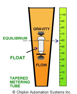
The rotameter is the most extensively employed variable area flowmeter. A rotameter is basically constructed of a vertically oriented glass or plastic tapered tube and a metering float which is free to move within the tube. Rotameters are although classified as differential pressure units but in actuality they are constant differential pressure devices. Flanged-end fittings offer a simple means for installing them in pipes. When there is no fluid flow, the float rests freely at the bottom of the tube. When liquid enters the bottom of the tube, the metering float begins to rise. The position of the float changes directly with the flow rate. The accurate position of the float is at the point where the differential pressure between the upper and lower surfaces balances the weight of the float. The greater the flow, the higher the float gets lifted. In case of fluids, the float rises due to a combination of the buoyancy of the liquid and the velocity head of the fluid whereas with gases, buoyancy is insignificant, and the float reacts by and large to the velocity head. A typical Rotameter is shown in the figure below:
Main Features
- In rotameters, the height of the float is an indication of the flow rate.
- The rotameter tube can be calibrated and graduated in suitable flow units.
- The rotameter usually have a Turndown Ratio up to 12:1.
- Accuracy may be as good as 1% of full scale rating.
- Rotameter tubes can be made from glass, metal, or plastic.
- Tube diameters range from 1/4 to greater than 6 in.
- In safe applications such as air or water rotameter tubes can be made of glass, whereas in situations where a breakage can result in an unsafe condition, they are provided with metal tubes.
- Besides, for higher pressures and temperatures above the practical range of glass, metal tube rotameters are employed.
- Plastic-tube rotameters are moderately low cost rotameters. Also, they are perfect for applications involving corrosive fluids or deionized water.
- Almost all rotameters are rather insensitive to viscosity variations. The most sensitive are extremely small rotameters with ball floats, while larger rotameters are not much sensitive to viscosity effects.
- Rotameters comprising magnetic floats can be used for alarm and signal transmission functions.
- Since the flow rate can be read directly on a scale mounted next to the tube, no secondary flow-reading devices are required. But still, if wanted, automatic sensing devices can be used to sense the float’s level and transmit a flow signal.
- For a particular fluid’s density and viscosity, every float position corresponds to a particular flowrate. Consequently, it is crucial to size the rotameter for each application. When sized properly, the flow rate can be determined by matching the float position to a calibrated scale on the outside of the rotameter.
- Lots of rotameters are available with a built-in valve for adjusting flow manually.
- Numerous shapes of float are available for various applications. One of the early float designs had slots, which caused the float to spin for stabilizing and centering purposes. Because of this rotation of the float, the term rotameter was coined.
Sizing of Rotameter
Rotameters are generally provided with calibration data and a direct reading scale for air or water or both. For sizing a rotameter for other service, one must first change the actual flow to a standard flow. In case of liquids the standard flow is meant to be the water equivalent in gpm whereas when gases are concerned, then the intended standard flow is the air flow equivalent in standard cubic feet per minute (scfm).
Tables listing standard water equivalent gpm and air scfm values are supplied by rotameter manufacturers. They are also supposed to make available slide rules, nomographs, or computer software which is often needed for sizing of rotameter.
Advantages
Major advantages of Rotameter are mentioned below:
- Low cost
- Simplicity
- Low pressure drop
- Quite wide rangeability
- Linear output
Sources
