
GF Rotameter
GF Rotameter
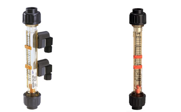
The plastic variable area flowmeters in the SK series from GF Piping Systems are radially-installed dismountable meters for measuring the rate of flow in industrial pipework applications.
The measurement ranges, which are attuned to our customers’ needs, and the range of materials available for the tubes and screwed fittings, meaning that the flow meters can be used for a wide range of applications and a great variety of media.
What is Rotameter?
Rotameters are the most widely used type of variable-area (VA) flowmeter. In these devices, the falling and rising action of a float in a tapered tube provide a measure of flow rate. Rotameters are known as gravity-type flowmeters because they are based on the opposition between the downward force of gravity and the upward force of the flowing fluid. When the flow is constant, the float stays in one position that can be related to the volumetric flow rate. That position is indicated on a graduated scale. Note that to keep the full force of gravity in effect, this dynamic balancing act requires a vertical measuring tube.
Other forms of gravity-type VA meters may incorporate a piston or vane that responds to flow in a manner similar to the float’s behavior. All these devices can be used to measure the flow rates of most liquids, gases, and steam. There are also similar types that balance the fluid flow with a spring rather than the gravitational force. These do not require vertical mounting, but corrosive or erosive fluids can damage the spring and lead to reduced accuracy.
When there is no flow through a rotameter, the float rests on the bottom of the dosing tube, where the maximum diameter of the float is approximately the same as the inner diameter of the tube. When the fluid enters the dosing tube, the floating effect of the fluid lightens the float. However, the float has a greater density than the fluid, and the flotation effect is not sufficient to raise it.
There is a small annular opening between the float and the tube. The pressure falling through the float increases and increases the float. This increases the area between the float and the tube until the upward hydraulic forces acting on it are balanced by their weight, less the floating force. The float moves up and down the tube in proportion to the flow rate of fluid and the annular area between the float and the tube. Reach a stable position in the tube when the forces are in equilibrium.
Technical Features
Size:
⅜”–2½”
Total Flow Range
- 0.01–264 GPM
Tube Material
- PA
- PSU
- PVC transparent
Seal
- EPDM
- FPM
Float
- PVDF
- PVDF-HP transparent
End Connection
- Solvent cement socket
- threaded
- flanged
- fusion spigot union
- fusion socket union
Range:
- d16 to d75: DN10 to DN65
Connections:
- Solvent Cement Socket
- Fusion Socket
Standards:
- ISO
- BS
- ASTM
- JIS
Nominal pressure:
- PN10
Fields of Application:
- Industrial Water Treatment
- Marine
- Automotive Industry
- Power Supply
- Food and Beverage
Advantages:
- No auxiliary energy required
- Easy reading off value
- Wide product range
Data Sheet
![]()


Leave a Reply
Want to join the discussion?Feel free to contribute!